Mobile relay protection test power supply device

A technology for relay protection and test power supply, which is applied in the direction of output power conversion devices, electrical components, electrical equipment structural parts, etc., and can solve problems such as increasing output power, malfunctioning relay protection, and abnormal DC system.

Active Publication Date: 2018-06-22
STATE GRID ZHEJIANG ELECTRIC POWER CO LTD JINHUA POWER SUPPLY CO +1
View PDF4 Cites 0 Cited by
  • Summary
  • Abstract
  • Description
  • Claims
  • Application Information

AI Technical Summary

Problems solved by technology

[0004] 1. The grounding of the DC circuit during the commissioning and installation process causes the abnormality of the DC system. If there is another grounding point in the substation, it may cause the protection device to malfunction or the switch to trip by mistake, causing a power grid accident.
[0005] 2. If the AC circuit is connected to the DC circuit in series, it may cause relay protection malfunction, and in severe cases, it will cause large-scale power outages.
[0007] 1. The output power is small, which cannot meet the actual power supply needs in the process of protection and transformation or infrastructure projects
In this case, we generally adopt the method of batch-by-batch power debugging for new devices, which often affects the efficiency of on-site work
[0008] 2. The wiring is inconvenient and there is only one power supply output: the power supply of the DC generator has no special external terminal and special wiring, and the wiring is time-consuming
One power output cannot meet large-scale renovation and infrastructure work
[0009] The solution to this problem is actually to increase the output power, which will lead to an oversized power supply. If the volume is small, heat dissipation will be a very serious problem, and if the volume is too large, it will not be able to reflect the convenience of movement.

Method used


Image

  • Mobile relay protection test power supply device
  • Mobile relay protection test power supply device
  • Mobile relay protection test power supply device

Examples


Embodiment Construction

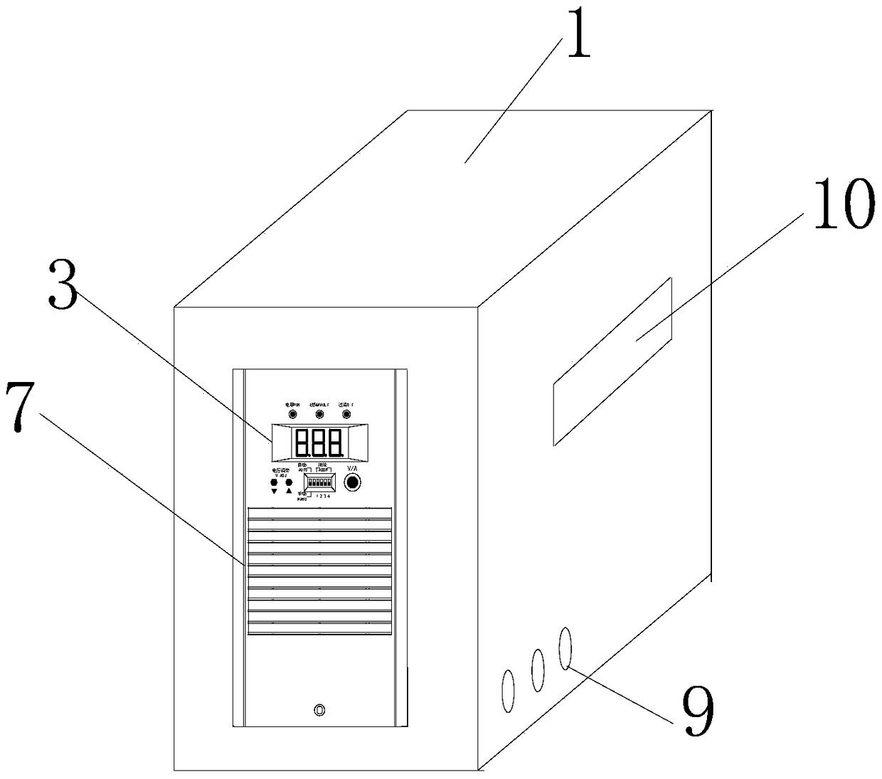
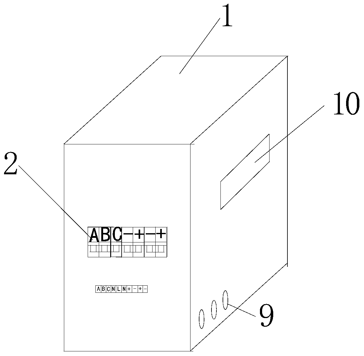
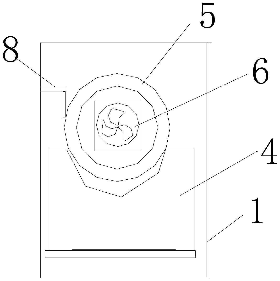
[0022] Such as figure 1 , figure 2 The present invention discloses a mobile relay protection test power supply device as shown, comprising a square housing 1, a control panel 3 is provided on the front of the housing 1, a wiring panel 2 is provided on the back of the housing 1, and a wiring panel 2 is provided on the back of the housing 1. A circuit board is installed in 1, and a rectifier module 4 is installed on the circuit board, such as image 3 As shown, the section of the rectification module 4 is U-shaped. The inside of the housing 1 is also provided with a spiral wiring channel 5. The spiral wiring channel 5 passes through the rectification module 4 and runs through the entire housing 1. The cables in the housing 1 are all laid in the spiral wiring channel 5. There is also a fan 6 inside the casing 1, the fan 6 is facing the center of the spiral wiring channel 5, and a heat dissipation grid 7 is opened under the control panel 3 on the front of the casing 1. A hange...


PUM


Abstract

The invention provides a mobile relay protection test power supply device, especially designs an internal heat radiation structure. The heat radiation performance of the power supply device is greatly improved on the premise of not increasing the size of the product; therefore, the power of the mobile power supply is improved. In order to realize the purpose, the mobile relay protection test power supply device provided by the invention is characterized in that a circuit board is installed in a shell body; a rectifier module is installed on the circuit board; the cross section of the rectifier module is U-shaped; a spiral wiring channel is arranged in the shell body; the spiral wiring channel passes through the rectifier module and penetrates the whole shell body; through the arrangement, the power of the mobile relay protection test power supply device provided by the invention is increased on the premise of reducing the size as much as possible, and the heat radiation problem is unnecessarily worried. The temperature on the control panel is monitored immediately; and the integral performance of the product is improved.

Description

technical field [0001] The invention relates to electric equipment, in particular to a mobile relay protection test power supply device. Background technique [0002] At this stage, there are two main methods for AC and DC power supply on the engineering site: [0003] The first one is to directly connect the newly installed relay protection device to the AC and DC power sources in the substation, which may cause two types of problems: [0004] 1. During the commissioning and installation process, the grounding of the DC circuit will cause the abnormality of the DC system. If there is another grounding point in the substation, it may cause the protection device to malfunction or the switch to trip by mistake, causing a power grid accident. [0005] 2. If the AC circuit is connected in series with the DC circuit, it may cause a malfunction of the relay protection, and in severe cases, it may cause a large-scale power outage. [0006] The second is to use the power generated...

Claims


Application Information

Patent Timeline
Patent Type & Authority Patents(China)
IPC IPC(8): H02M1/10H02M7/02H05K7/20
CPCH02M1/10H02M7/02H05K7/20136
Inventor 施川吴乐军吴雪峰叶玮邓方远梅杰张一航赵寿生方旭光江应沪吴杰清金慧波钱逸轩
Owner STATE GRID ZHEJIANG ELECTRIC POWER CO LTD JINHUA POWER SUPPLY CO
Why Eureka
Try Eureka