
Screw barrel cooling device

A technology of cooling device and screw barrel, which is applied in the field of extruders, can solve the problems of low temperature, different heat dissipation effects, and inability to ensure uniform cooling, and achieve the effect of uniform cooling and uniform temperature

Active Publication Date: 2016-05-11
镇江越升智能装备制造有限公司
View PDF6 Cites 2 Cited by
  • Summary
  • Abstract
  • Description
  • Claims
  • Application Information

AI Technical Summary

Problems solved by technology

[0004] Although the heating device of the above-mentioned medical pipe extruder can heat the barrel evenly, when the temperature is too high, the fan will cool down the barrel, and the wind generated by the fan will reach the maximum temperature according to the distance. The heat dissipation effect is also different, which makes it impossible to ensure uniform cooling of the barrel when cooling down, which leads to the barrel near the fan position preferentially reaching the required temperature value, while the end far away from the fan cannot drop to the required temperature value. , so that the fan needs to continue to work, which will cause the temperature of the barrel close to the fan to be lower than the stated temperature value, making it difficult to quickly adjust the temperature in the barrel

Method used


Image

  • Screw barrel cooling device
  • Screw barrel cooling device
  • Screw barrel cooling device

Examples


Embodiment 1

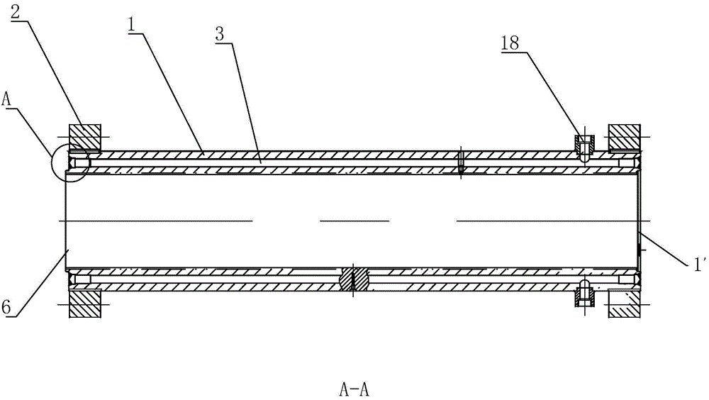
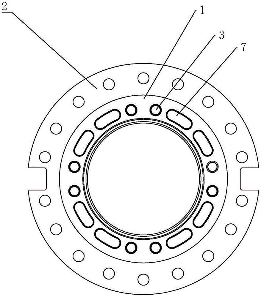
[0037] Embodiment 1: a kind of screw barrel cooling device, such as image 3 , 5As shown, it includes the screw barrel 1 and the connecting flange 2 plates at both ends of the screw barrel 1. The wall of the screw barrel 1 is provided with a number of first holes that run through both ends of the screw barrel 1 and are parallel to the axis of the screw barrel 1. A cooling channel 3 and a second cooling channel 4, the first cooling channel 3 and the second cooling channel 4 are evenly distributed on the screw barrel 1 in the circumferential direction, the first cooling channel 3 and the second cooling channel The two cooling channels 4 are arranged at intervals, and one end of the screw barrel 1 is provided with a first circulation groove 5 for the medium circulation in the adjacent first cooling channel 3 and the second cooling channel 4, and the other end is provided with a The second flow groove 6 connecting the second cooling flow channel 4 with another adjacent first cool...

Embodiment 2

[0044] Embodiment 2: The difference from Embodiment 1 is that first heat exchange blades 14 are helically arranged on the inner wall of the first cooling channel 3 along the axial direction of the first cooling channel 3 . Through the first heat exchange vanes 14 arranged on the inner wall of the first cooling channel 3, the medium flows in a spiral manner during the circulation process, which increases the circulation path of the medium and enables the medium to more fully communicate with the first cooling channel. The inner wall of a cooling channel 3 is in contact with the first heat exchanging blade 14, so that the medium can take away more heat during the circulation process, thereby achieving the purpose of rapid cooling. Second heat exchange blades 15 are helically arranged on the inner wall of the second cooling channel 4 along the axial direction of the second cooling channel 4 . By adopting the above-mentioned technical solution, the second heat exchange blade 15 pr...


PUM


Abstract

The invention discloses a screw barrel cooling device and an extruder with the device, and belongs to the field. The screw barrel cooling device and the extruder with the device aim at evenly lowering the temperature in a charging barrel. According to the technical scheme, the screw barrel cooling device comprises a screw barrel and connecting flange plates at the two ends of the screw barrel. A plurality of first cooling channels and second cooling channels which penetrate the two ends of the screw barrel and are parallel to the axis of the screw barrel are arranged in the wall of the screw barrel. Water channel cover plates for preventing circulating media from being leaked are arranged on first circulating grooves and second circulating grooves. Cooling and circulating channels are formed by the first cooling channels and the second cooling channels through the first circulating grooves and the second circulating grooves, the four sets of cooling and circulating channels are arranged on the screw barrel in a circumferential array manner, and input holes and output holes communicating with the cooling and circulating channels end to end are formed in the screw barrel.

Description

technical field [0001] The invention relates to an extruder, in particular to a screw barrel cooling device. Background technique [0002] The heating system of the extruder generally uses the traditional resistance heating method to heat the raw materials in the barrel, which not only consumes a lot of power, but also produces serious heat pollution, low heat conversion efficiency, and 60% of the heat is lost Therefore, it is necessary to use a flow fan for cooling in the production workshop, which increases the cost of production and operation of the enterprise. At the same time, it is difficult for the traditional heating device to heat evenly, which greatly reduces the working reliability of the extruder. [0003] The Chinese patent with the application number 201510426197.X discloses a heating device for a medical pipe extruder, which includes a barrel, and several temperature measuring tanks are uniformly arranged on the barrel, and the temperature measuring tank is pr...

Claims


Application Information

Patent Timeline
IPC IPC(8): B29C47/80
CPCB29C48/834
Inventor 张海军
Owner 镇江越升智能装备制造有限公司
Features
  • Generate Ideas
  • Intellectual Property
  • Life Sciences
  • Materials
  • Tech Scout
  • Unparalleled Data Quality
  • Higher Quality Content
  • 60% Fewer Hallucinations
Learn More