Molten tin bath bottom-brick structure

A tin bath bottom brick and tin bath technology, applied in the field of trough bottom brick structure, can solve the problems of high power usage of electric heating, displacement of movable fixed edge bricks, and inability to achieve predetermined functions, etc., so as to reduce temperature and reduce The amount used, the effect of reducing the amount of tin penetration

Inactive Publication Date: 2016-05-11
YICHANG CSG PHOTOELECTRIC GLASS
View PDF0 Cites 2 Cited by
  • Summary
  • Abstract
  • Description
  • Claims
  • Application Information

AI Technical Summary

Problems solved by technology

[0002] At present, the bottom brick structure of the tin tank used in the ultra-thin float glass production line is a single-layer structure, and the fixed side bricks are movable and the graphite lining structure is fixed by external fixing parts. During use, it is not conducive to heat preservation in the tank, and a large amount of heat is lost. As a result, the power used by electric heating remains high, especially when producing ultra-thin glass below 1.1mm. Due to various factors, the fixed side bricks and graphite lining are damaged or the displacement deviates, so the intended function cannot be realized.

Method used


Image

  • Molten tin bath bottom-brick structure
  • Molten tin bath bottom-brick structure

Examples


Embodiment Construction

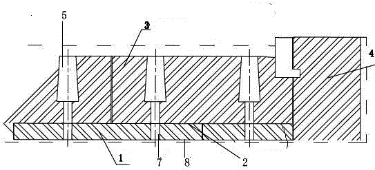
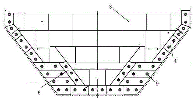
[0021] Such as figure 1 with figure 2 As shown, a tin bath bottom brick structure includes a tin bath bottom lining brick 1 arranged on the bottom steel plate of the tin bath,

[0022] The tin bath bottom brick 1 is provided with the tin bath bottom brick 3, the first anti-seepage layer 8 is arranged between the tin bath bottom brick 1 and the tank bottom steel plate, and the tin bath bottom brick 1 and the tin bath bottom brick 3 The second anti-seepage layer 2 is provided, the upper side of the tin bath bottom lining brick 1 is provided with a sealing hole 5, the tin bath bottom brick 3, the second anti-seepage layer 2, the tin bath bottom lining brick 1 and the bottom of the sealing hole 5 The first anti-seepage layer 8 is provided with a through hole 7, which is installed on the steel plate at the bottom of the tin tank through fixing bolts;

[0023] Both sides of the tin bath bottom brick 3 are fixedly connected with fixed side bricks, and the fixed side bricks are com...


PUM


Abstract

The invention discloses a molten tin bath bottom-brick structure. The molten tin bath bottom-brick structure comprises molten tin bath underlay bricks arranged on a tank bottom steel plate at the bottom of the molten tin bath, wherein the molten tin bath bottom bricks are arranged on the molten tin bath bottom underlay bricks; a first seepage-proof layer is arranged between the molten tin bath underlay bricks and the tank bottom steel plate; a second seepage-proof layer is arranged between the molten tin bath underlay bricks and the molten tin bath bottom bricks; tank sealing holes are formed in the upper sides of the molten tin bath underlay bricks; through holes are formed in the molten tin bath bottom bricks, the second seepage-proof layer and the molten tin bath underlay bricks, which are located below the tank sealing holes, and the molten tin bath bottom bricks, the second seepage-proof layer and the molten tin bath underlay bricks are mounted on the tank bottom steel plate at the bottom of the molten tin bath through fixing bolts; fixed side-locating bricks are fixedly connected with the both sides of the molten tin bath bottom bricks, and comprise side wall bricks and inverted-Y-shaped bricks located on the inner sides of the side wall bricks; graphite linings are arranged between the side wall bricks and the molten tin bath bottom bricks. The molten tin bath bottom-brick structure provided by the invention can overcome the defect in the prior art, realize molten tin bath insulation, save energy, reduce consumption, and meanwhile completely solve the adverse effect caused by displacement bias of the side-locating bricks and the graphite linings.

Description

technical field [0001] The invention relates to the field of ultra-thin glass production, in particular to a tin bath bottom brick structure used in ultra-thin glass production. Background technique [0002] At present, the bottom brick structure of the tin tank used in the ultra-thin float glass production line is a single-layer structure, and the fixed side bricks are movable and the graphite lining structure is fixed by external fixing parts. During use, it is not conducive to heat preservation in the tank, and a large amount of heat is lost. As a result, the power used by electric heating remains high, especially when producing ultra-thin glass below 1.1mm. Due to various factors, the movable fixed side brick and graphite lining are damaged or the displacement deviates, so the intended function cannot be realized. Contents of the invention [0003] The technical problem to be solved by the present invention is to provide a tin bath bottom brick structure, which can ov...

Claims


Application Information

Patent Timeline
Patent Type & Authority Applications(China)
IPC IPC(8): C03B18/16
Inventor 曾南刘沐阳孙亚明陈健
Owner YICHANG CSG PHOTOELECTRIC GLASS
Why Eureka
Try Eureka