
Rain gauge capable of flow distribution and monitoring

A rain gauge and rainfall technology, applied in the field of rain gauge, can solve the problem of no diversion effect, etc., and achieve the effect of preventing rainwater from overflowing and water flow slowing down.

Inactive Publication Date: 2016-05-11
WUXI NUIST WEATHER SENSOR NETWORK TECH
View PDF7 Cites 12 Cited by
  • Summary
  • Abstract
  • Description
  • Claims
  • Application Information

AI Technical Summary

Problems solved by technology

The rainwater flow is slowed down by setting double-layer tipping buckets to achieve the purpose of reducing the error, but the above structure still only uses areas with little rainwater, and when the water flow is large, it does not have a good diversion effect

Method used


Image

  • Rain gauge capable of flow distribution and monitoring

Examples


Embodiment 1

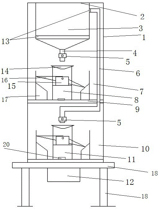
[0022] Such as figure 1 As shown, a rain gauge capable of diverting monitoring includes a casing 1, and a middle partition 9 is arranged inside the casing 1 to divide the casing 1 into two chambers, and 2 water receiving ports at the top of the casing 1 are provided There is a water storage tank 3, and the bottom of the water storage tank 3 is provided with a water outlet pipe 4, and a throttle valve 5 is installed on the water outlet pipe 4 to control the flow rate of the water flow. A first rainfall measuring device 7 is provided below the water storage tank 2 for measuring and calculating For the rainfall data, the first rainfall measuring device 7 includes the first rain sensing device 8, and the first rain measuring device 7 is installed on the intermediate partition 9; the upper end of the side wall of the water storage tank 3 is provided with a shunt pipe 6, for To prevent the outlet pipe 4 and the shunt pipe 6 from being blocked by impurities, the bottom of the water s...

Embodiment 2

[0024] In order to increase the durable time of the rain gauge in the present invention, and make this scheme meet the actual demand, the above-mentioned scheme is further limited:

[0025] Such as figure 1As shown, a rain gauge capable of shunting monitoring includes a casing 1, the casing 1 is a stainless steel outer cylinder, and a middle partition 9 is arranged inside the casing 1, which divides the casing 1 into two chambers. A water storage tank 3 is provided at the water receiving port 2 on the top of the body 1. The inner diameter of the rain receiving port is Φ203mm. The bottom of the water storage tank 3 is provided with a water outlet pipe 4, and a throttle valve 5 is installed on the water outlet pipe 4 to control the flow rate of the water flow. The bottom of the water tank 2 is provided with a first rainfall measuring device 7 for measuring and calculating rainfall data. The first rain measuring device 7 includes a first rain sensing device 8, and the first rain ...


PUM


Abstract

The invention relates to a rain gauge capable of flow distribution and monitoring. The rain gauge comprises a shell, a middle separating plate is arranged in the shell, a water-bearing opening at the top of the shell is provided with a water storage tank, the bottom of the water storage tank is provided with a water-outlet pipe, the water-outlet pipe is provided with a throttle valve, a first rainfall measuring device is arranged below the water storage tank, the first rainfall measuring device comprises a first rainfall sensing device, the first rainfall measuring device is arranged on the middle separating plate, the upper end of a sidewall of the water storage tank is provided with a flow-distribution pipe, the flow-distribution pipe penetrates through the middle separating plate, a water outlet of the flow-distribution pipe is arranged below the middle separating plate, a second rainfall measuring device is arranged below the water outlet, the second rainfall measuring device comprises a second rainfall sensing device, the shell is also provided with a processing system, and the processing system is connected with the first rainfall sensing device and the second rainfall sensing device. According to the rain gauge, the flow-distribution pipeline and the second rainfall measuring device are provided so that the rainfall can still be accurately measured in regions with heavy rainfall, the structure is simple, and the usage is convenient.

Description

technical field [0001] The invention belongs to the field of meteorological monitoring, in particular to a rain gauge capable of diverting monitoring. Background technique [0002] Precipitation is a measure of how much rain falls in an area. The total amount of water vapor contained in the air column is also known as the precipitable amount of water. It corresponds to the amount of precipitation that can be formed when all the moisture in the air condenses into rain and snow. [0003] There are many types of rain gauges, the common ones are siphon rain gauge, weighing rain gauge, tipping bucket rain gauge and so on. [0004] The tipping bucket rain gauge is a telemetry rainfall instrument composed of sensors and signal recorders. Clock, control circuit board and other components. Its working principle is: rainwater enters the water receiver from the uppermost water receiving port, falls into the water receiving funnel, and flows into the tipping bucket through the funne...

Claims


Application Information

Patent Timeline
Patent Type & Authority Applications(China)
IPC IPC(8): G01W1/14
CPCG01W1/14
Inventor 禹胜林
Owner WUXI NUIST WEATHER SENSOR NETWORK TECH
Learn More