Photoelectric Earth Projector

A projector and earth technology, applied in planetariums/globes, instruments, educational appliances, etc., can solve problems such as limitation of intuition, inability to realize spherical surface projection, etc., and achieve intuitive and convenient display effect

Active Publication Date: 2017-12-26
山东顺瑞商贸有限公司
View PDF5 Cites 0 Cited by
  • Summary
  • Abstract
  • Description
  • Claims
  • Application Information

AI Technical Summary

Problems solved by technology

[0002] Some of the current electronic globes already have functions such as touch control and projection, but the current globes can only project on walls or screens, but cannot project on the surface of a sphere, and cannot directly touch the sphere to make geographic images directly Scales on a sphere, so its intuitiveness is more limited

Method used


Image

  • Photoelectric Earth Projector
  • Photoelectric Earth Projector

Examples


Embodiment 1

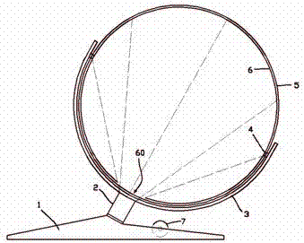
[0013] exist figure 1 In the first shown embodiment, the photoelectric globe projector includes a base 1; a tilting shaft 2 is fixed above the base 1, and the tilting shaft 2 is connected to a semi-circular support 3 that can rotate around the tilting shaft; A polar axis 4 orthogonal to the tilt axis 2 is fixed on the annular support 3; the polar axis 4 is pivotally connected to the north and south poles of the model sphere 5 of the earth, and the model sphere 5 can freely rotate around the polar axis 4; The inside of the inclined axis 2 is provided with a projection lens (not shown) that projects along the axis to the model sphere 5, and the projection optical path of the projection lens is as follows: figure 1 Shown in the dotted line in the center; the model sphere 5 is fully transparent, and the inside of the model sphere 5 is also provided with a spherical shell 6 whose surface is close to the model sphere 5 and concentric with the model sphere; the spherical shell 6 is m...

Embodiment 2

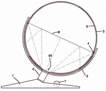
[0018] for figure 2 The difference between the illustrated embodiment two and the first embodiment is that a piece of photoelectric glass 8 that coincides with the interface and covers the entire interface inside the spherical shell is also fixed in the spherical shell 6. The photoelectric glass 8 is a mirror surface when it is powered on, and it is transparent when it is powered off; Projection, the geographical image is displayed on the upper hemisphere; when the photoelectric glass 8 is a mirror surface, the geographical image corresponding to the lower hemisphere of the model sphere below the interface is projected forward through the projection lens, so that the geographical image passes through After the photoelectric glass 8 is reflected, it is displayed on the lower hemisphere.

[0019] The photoelectric glass 8 is powered by a pulse current, so that the conversion frequency between the mirror surface and the transparent state reaches more than 75 Hz, thereby reachin...


PUM


Abstract

The invention provides a photoelectric globe projector, which comprises a base. An inclined shaft is fixedly arranged on the base; the inclined shaft is connected with a half-ring support capable of rotating around the inclined shaft; the half-ring support is fixedly provided with pole shafts orthogonal with the inclined shaft; the pole shafts are pivoted at the north and south poles of a model ball body of the earth; the model ball body can rotate freely around the pole shafts; the inclined shaft is internally provided with a projection lens for projecting to the model ball body along the axis; the model ball body is fully transparent and is internally provided with a ball housing; the ball housing is made of screen material and is relatively fixed with the pole shafts; the ball housing is provided with a light pass hole in the place right facing to the projection lens, so that light beams emitted from the projection lens can cover the upper half ball of the model ball body; the projection lens is coupled to a projection host in the base; the model ball body is matched with a space angle sensing system; and the projection host generates a projection image according to the space angle of the model ball body. The projector can realize geographic image projection on the model ball body and can enable geographic images to be directly zoomed on the surface of the model ball body.

Description

technical field [0001] The invention relates to the field of photoelectric geography demonstration equipment, in particular, it is a photoelectric earth projector. Background technique [0002] Some of the current electronic globes already have functions such as touch control and projection, but the current globes can only project on walls or screens, but cannot project on the surface of a sphere, and cannot directly touch the sphere to make geographic images directly Scales on a sphere, so its intuition is somewhat limited. Contents of the invention [0003] In view of the above problems, the object of the present invention is to provide a photoelectric earth projector, which can project geographic images on a model sphere, and can directly scale the geographic images on the surface of the model sphere. [0004] The technical solution adopted by the present invention to achieve the technical purpose is: the photoelectric globe projector includes a base; a tilting shaft i...

Claims


Application Information

Patent Timeline
Patent Type & Authority Patents(China)
IPC IPC(8): G09B27/08
CPCG09B27/08
Inventor 朱小菊
Owner 山东顺瑞商贸有限公司
Why Eureka
Try Eureka