A battery protection system

A protection system and battery technology, applied in the direction of battery overcharge protection, battery overcurrent protection, battery overdischarge protection, etc., can solve the problems of large PCB board space, inability to fully integrate, and difficulty in integrating protection ICs, etc., to reduce PCB The effect of reducing area, reducing heat generation, and reducing impedance

Active Publication Date: 2018-06-19
ZAOZHUANG HANQI COMM TECH CO LTD
View PDF2 Cites 4 Cited by
  • Summary
  • Abstract
  • Description
  • Claims
  • Application Information

AI Technical Summary

Problems solved by technology

[0006] (1) A total of three ICs, one protection IC and two MOSs, are required to implement, and the system cost is high;
[0007] (2) The two MOSs have a large area and are difficult to integrate into the protection IC. They cannot be fully integrated and require a larger PCB board space. This is contrary to the trend of smaller and lighter portable devices;

Method used


Image

  • A battery protection system
  • A battery protection system
  • A battery protection system

Examples


Embodiment 1

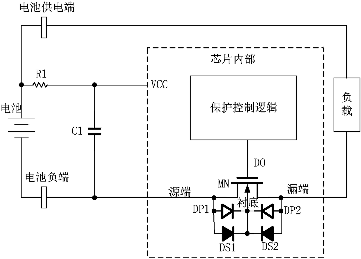
[0022] Such as image 3 , the battery protection system in this embodiment includes a protection control logic module, an N-channel MOS transistor MN, a Schottky diode DS1 and a Schottky diode DS2. in image 3 Among them, DP1 and DP2 are the parasitic diodes between the source and the substrate of the NMOS transistor MN, and the drain and the substrate respectively. The output terminal of the protection control logic module is connected to the gate of MN, the negative poles of DS1 and DS2 are connected to the substrate, and the positive poles of DS1 and DS2 are respectively connected to the source and drain of the N-channel MOS transistor MN. The system leads to the VCC pin of the power supply, the source and drain of the N-channel MOS tube, where VCC is connected to the positive pole of the battery after the resistor R1 is connected in series, the source of MN is connected to the negative pole of the battery, and the drain of MN is connected to the positive pole of the batt...


PUM


Abstract

The invention provides a battery protection system, which is formed by a protection and control logic module, an N-channel MOS transistor MN, a Schottky diode DS1 and a Schottky diode DS2. The output end of the protection and control logic module is connected with the grid electrode of the MN; the positive electrode of the DS1 and the positive electrode of the DS2 are connected with the source electrode and the drain electrode of the MN respectively; and the negative electrode of the DS1 and the negative electrode of the DS2 are connected on the substrate. The battery protection system leads out a power supply VCC pin and the source electrode and the drain electrode of the MN; the power supply VCC pin is connected with the positive electrode of a battery, and the source electrode of the MN is connected with the negative electrode of the battery; and a load is connected between the positive electrode of the battery and the drain electrode of the MN. The low-cost and full-integration battery protection system is realized; the system only need one power MOS, and thus the cost of a lithium battery protection system is greatly reduced; impedance can be reduced and heat can be reduced with only one power MOS; the whole protection system is integrated in one IC, thereby reducing the area of a PCB; and the back-to-back Schottky diodes are utilized to realize NMOS MN substrate voltage automatic switching, and any electric leakage path does not exist.

Description

【Technical field】 [0001] The invention relates to the technical field of batteries, in particular to a battery protection system. 【Background technique】 [0002] In recent years, lithium-ion batteries have been widely used in portable products such as smartphones and wearable devices. In the case of overcharging, over-current discharge, over-discharge, etc., lithium-ion batteries may be aging, catch fire or even explode. Therefore, when using lithium-ion batteries, it is necessary to add a battery protection chip. [0003] figure 1 It is an existing battery protection system, which is mainly realized by traditional battery protection IC and external discharge NMOS MN1 and charge NMOS MN2. Wherein DP1 and DP2 are parasitic diodes of MN1 and MN2 respectively. Its working principle is as follows: when charging the battery and discharging the load normally, the protection IC controls MN1 and MN2 to turn on to realize the function. When the load is short-circuited, the prote...

Claims


Application Information

Patent Timeline
Patent Type & Authority Patents(China)
IPC IPC(8): H02J7/00
CPCH02J7/0026H02J7/00302H02J7/00304H02J7/00306
Inventor 刘陵刚
Owner ZAOZHUANG HANQI COMM TECH CO LTD
Why Eureka
Try Eureka