
A vacuum carbon tube furnace heating terminal

A carbon tube furnace and terminal technology, applied in ohmic resistance heating parts, ohmic resistance electrodes, etc., can solve the problem of low heating efficiency of heating terminals, and achieve the effect of improving heating efficiency

Active Publication Date: 2018-11-16
TANGZHOU QIANGMING ELECTROTHERMAL APPLIANCE CO LTD
View PDF3 Cites 0 Cited by
  • Summary
  • Abstract
  • Description
  • Claims
  • Application Information

AI Technical Summary

Problems solved by technology

However, the heating efficiency of the heating terminals of the commonly used vacuum carbon tube furnaces is not high.

Method used


Image

  • A vacuum carbon tube furnace heating terminal
  • A vacuum carbon tube furnace heating terminal

Examples


Embodiment Construction

[0012] The preferred embodiments of the present invention will be described in detail below in conjunction with the accompanying drawings, so that the advantages and features of the present invention can be more easily understood by those skilled in the art, so as to define the protection scope of the present invention more clearly.

[0013] The invention provides a heating terminal of a vacuum carbon tube furnace with higher heating efficiency.

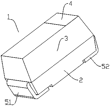
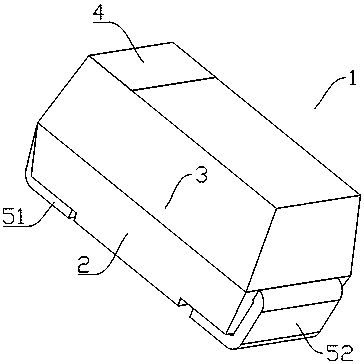
[0014] Such as figure 1 , figure 2 As shown, a heating terminal 1 of a vacuum carbon tube furnace includes a fixed body 2, a heating body 3 is arranged on the fixed body 2, and a heat dissipation layer 4 is arranged on the surface of the heating body 3. A first fixed electrode 51 and a second fixed electrode 52 are respectively provided at both ends of the fixed body 2 described above.

[0015] Such as figure 1 , figure 2 As shown, the heating element 3 and the fixed body 2 are slidingly connected.

[0016] Such as figure 1 ,...


PUM


Abstract

The invention discloses a vacuum carbon tube furnace heating terminal, which comprises a fixed body, wherein the fixed body is provided with a heating body; a cooling layer is arranged on the surface of the heating body; a first fixed electrode and a second fixed electrode are arranged at two ends of the fixed body; the heating body and the fixed body are in sliding connection; and the first fixed electrode and the second fixed electrode are made of copper. According to the vacuum carbon tube furnace heating terminal disclosed by the invention, the fixed body is arranged on a body; the heating body in sliding connection is arranged on the fixed body; the cooling layer is arranged on the surface of the heating body and can emit heat generated by the heating body as quickly as possible; and meanwhile, the two fixed electrodes are also arranged at the bottom part of the fixed body, so that the heating efficiency of the vacuum carbon tube furnace heating terminal is greatly improved.

Description

technical field [0001] The invention relates to a heating terminal, more precisely, a heating terminal of a vacuum carbon tube furnace. Background technique [0002] Vacuum carbon tube furnace is a kind of industrial equipment that is widely used in industrial production and has a broad application prospect. However, the heat generation efficiency of the heating terminal of the generally used vacuum carbon tube furnace is not high. Contents of the invention [0003] The invention mainly solves the technical problems existing in the prior art, thereby providing a heating terminal of a vacuum carbon tube furnace with higher heating efficiency. [0004] Above-mentioned technical problem of the present invention is mainly solved by following technical scheme: [0005] A heating terminal of a vacuum carbon tube furnace, comprising a fixed body, a heating body is arranged on the fixing body, a heat dissipation layer is arranged on the surface of the heating body, and two ends ...

Claims


Application Information

Patent Timeline
Patent Type & Authority Patents(China)
IPC IPC(8): H05B3/03
CPCH05B3/03
Inventor 华国洋
Owner TANGZHOU QIANGMING ELECTROTHERMAL APPLIANCE CO LTD
Learn More