
Shoe with shoe lace tightness capable of being automatically adjusted

An automatic adjustment and shoelace technology, applied in footwear, fasteners, clothing, etc., can solve the problems of cumbersome time-consuming, troublesome, pain, etc., and achieve the effect of reasonable design, convenient wearing and taking off, and improved comfort.

Active Publication Date: 2016-05-18
黄逢春
View PDF7 Cites 12 Cited by
  • Summary
  • Abstract
  • Description
  • Claims
  • Application Information

AI Technical Summary

Problems solved by technology

Shoes with a shoelace structure need to be loosened and tightened when putting them on and taking off, which is cumbersome and time-consuming; seemingly easy to tie shoelaces, in many cases it is almost impossible for some people
Currently, the most common form is a criss-cross shoelace between the medial and lateral parts of the upper, which the wearer pulls tightly around the instep and knots; As the knot loosens naturally around the wearer's foot, the laces need to be tied and re-tied throughout the day, which can cause frustration for the average shoe wearer
Young children, in particular, may not know how to tie knots in shoelaces and need the help of a parent or caregiver; also, elderly people afflicted with arthritis pull shoelaces taut and tie knots in order to secure shoes to feet , may feel painful or unduly challenging; also, some people with disabilities or loss of finger dexterity, they also have difficulty tying thin shoelaces

Method used


Image

  • Shoe with shoe lace tightness capable of being automatically adjusted
  • Shoe with shoe lace tightness capable of being automatically adjusted
  • Shoe with shoe lace tightness capable of being automatically adjusted

Examples


Embodiment Construction

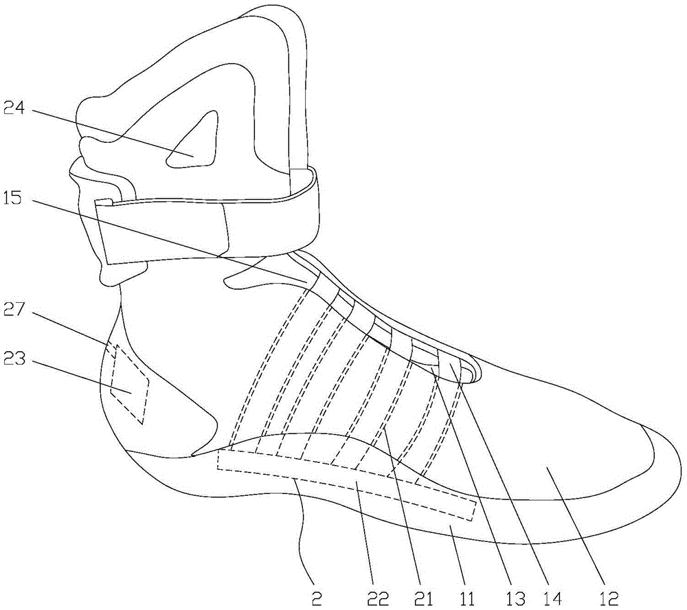
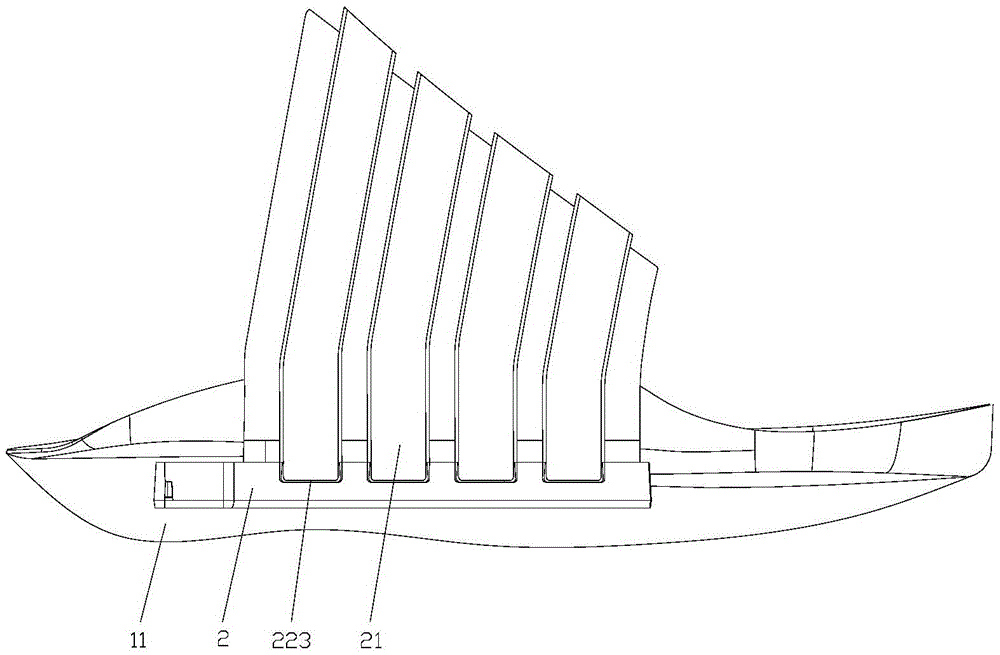
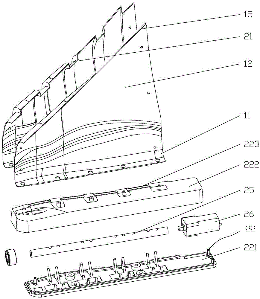
[0026] Such as Figure 1-3 As shown in one of them, the present invention comprises sole 11, vamp 12, shoe tongue 13 and several shoelaces 14, and vamp 12 is fixedly connected on the upper surface of sole 11, and the middle part of vamp 12 is provided with U-shaped opening 15, and shoe tongue 13 It is fixedly connected to the front end of the opening 15, and it also includes a hidden electric shoelace tying device 2. The hidden electric shoelace tying device 2 includes several guide rails 21, a protective case 22, a power supply 23 and a controller 24. The guide rails 21 are all arranged in the shoe upper 13 on one side of the opening 15, and extend from the side edge of the opening 15 to the direction of the sole 11. The protective shell 22 is arranged in the sole 11 on the same side as the guide rail 21. There is a shaft 25 and a motor 26 for driving the shaft 25 to rotate, the motor 26 is electrically connected to the power supply 23 arranged in the sole 11, and the control...


PUM


Abstract

The invention relates to a shoe with shoe lace tightness capable of being automatically adjusted. The shoe comprises a sole, a vamp, a shoe tongue and a plurality of shoe laces; the vamp is fixedly connected to the upper surface of the sole; a U-shaped opening is formed in the middle of the vamp; the shoe tongue is fixedly connected to the front end of an opening; the shoe further comprises a hidden electric shoe lacing binding device which comprises a plurality of guide rails, a protective shell, a power source and a controller; the guide rails are all arranged in the portion, on one side of the opening, of the vamp and extend to the sole from the edge of one side of the opening; the protective shell is arranged in the portion, on the same side as the guide rails, of the sole; a shaft rod and a motor used for driving the shaft rod to rotate are arranged in the protective shell; the motor is electrically connected with the power source arranged in the sole; the controller and the motor are connected and are used for controlling the motor to be powered on or off and the rotating direction of the motor; one end of each of the shoe laces is wound on and fixed to the shaft rod; the other end of each shoe laces penetrates the corresponding guide rail and is fixedly connected to the portion, on the other side of the opening, of the vamp; the controller controls the motor to rotate forwards and reversely, the motor drives the shaft rod to rotate forwards and reversely, and the tightness of the shoe laces is adjusted.

Description

technical field [0001] The invention relates to the technical field of shoes, in particular to a shoe that can automatically adjust the tightness of shoelaces. Background technique [0002] Nowadays, shoes are still necessary daily necessities for protecting feet, and along with the continuous improvement of people's requirements for quality of life, shoes of various styles and functions have sprung up like mushrooms after rain. [0003] For the putting on and taking off structure and comfort of shoes, most still maintain the shoelace structure. Shoes with a shoelace structure need to be loosened and fastened when they are put on and taken off, which is cumbersome and time-consuming; the seemingly easy tying of shoelaces is almost impossible for some people in many cases. Currently, the most common form is a criss-cross shoelace between the medial and lateral parts of the upper, which the wearer pulls tightly around the instep and knots; As the knot loosens naturally aroun...

Claims


Application Information

Patent Timeline
IPC IPC(8): A43C11/16
CPCA43C11/165
Inventor 黄逢春
Owner 黄逢春
Learn More