
A pneumatic punching machine for electronic connectors

An electronic connector and punching machine technology, applied in the field of mechanical processing, can solve the problems of failure to recycle waste, random stacking of waste, injury to staff, etc., and achieve the effects of convenient operation, high processing accuracy, and ensuring safety and hygiene.

Active Publication Date: 2018-07-20
苏州新实达精密电子科技有限公司
View PDF5 Cites 0 Cited by
  • Summary
  • Abstract
  • Description
  • Claims
  • Application Information

AI Technical Summary

Problems solved by technology

[0002] Common electronic connectors usually require through-holes or edge milling, etc. The current through-holes generally place the electronic connectors on a flat surface, and then manually make through-holes. This operation is not only slow, but also inaccurate. , has burrs, etc., and it is easy to injure the staff during the operation, and the waste generated during the through-hole process cannot be recycled, and the waste is piled up randomly, which affects the appearance and is prone to danger.

Method used


Image

  • A pneumatic punching machine for electronic connectors
  • A pneumatic punching machine for electronic connectors
  • A pneumatic punching machine for electronic connectors

Examples


Embodiment Construction

[0018] In order to deepen the understanding of the present invention, the present invention will be described in further detail below in conjunction with the accompanying drawings and embodiments, which are only used to explain the present invention and do not limit the protection scope of the present invention.

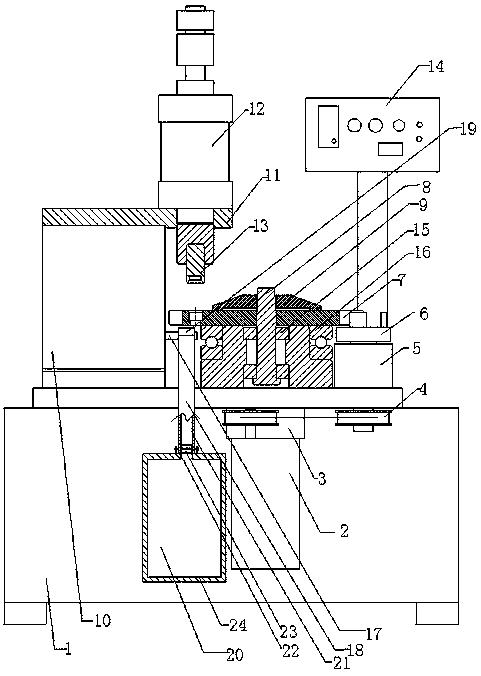
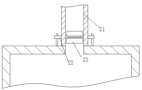
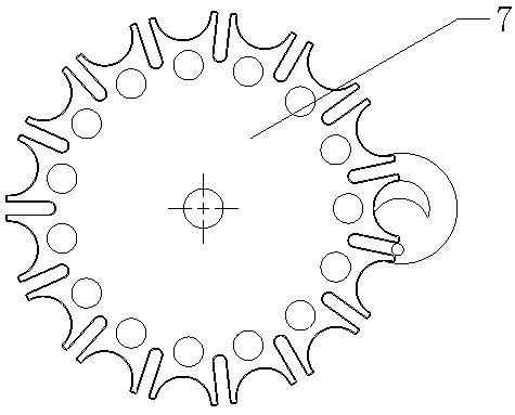
[0019] like Figure 1-4 As shown, the present invention is a pneumatic punching machine for electronic connectors, the punching machine includes a body 1, a control box 14 is arranged on the body 1, and the opening or closing of the equipment is controlled by the control box 14. The body 1 is provided with a motor fixing seat 3, on which a speed-regulating motor 2 is arranged, on the body 1 of the stamping machine, a disc 7 is arranged, and above the disc 7, a The disk presses the cap 9 to prevent the disk from exceeding the intermediate shaft, and the speed-regulating motor 2 drives the disk 7 to rotate through an intermediate shaft 8 and bearing 15, and places the ...


PUM


Abstract

The invention relates to an electronic connector pneumatic punching machine comprising a machine body; the machine body is provided with a control box and a motor mount; a speed regulation motor is arranged on the motor mount; the punching machine body is provided with a round disc; the speed regulation motor drives the round disc to rotate through a middle shaft and a bearing; the punching machine body is also provided with a cylinder support having a cylinder fixed plate; the cylinder fixed plate is provided with cylinder; a punching head is arranged below the cylinder; the cylinder support is also provided with a material groove rack; an oblique discharge slide groove is arranged on the material groove rack; the top of the discharge slide groove is provided with a waste material feeding port; the other end of the discharge slide groove is connected with a waste groove supported by the machine body. The electronic connector pneumatic punching machine is simple in structure, convenient in operation, reasonable in design, can improve processing speed, can ensure worker operation safety, and waste material can be recycled, thus providing energy saving environmental protection effect.

Description

technical field [0001] The invention belongs to the technical field of mechanical processing, and in particular relates to a stamping machine, in particular to a pneumatic stamping machine for electronic connectors. Background technique [0002] Common electronic connectors usually require through-holes or edge milling, etc. The current through-holes generally place the electronic connectors on a flat surface, and then manually make through-holes. This operation is not only slow, but also inaccurate. , There are burrs, etc., and it is easy to injure the staff during the operation, and the waste generated during the through-hole process cannot be recycled, and the waste is piled up randomly, which affects the appearance and is prone to danger. Contents of the invention [0003] In order to solve the above problems, the present invention provides a new type of pneumatic stamping machine with high processing speed and accurate processing. [0004] In order to achieve the abo...

Claims


Application Information

Patent Timeline
Patent Type & Authority Patents(China)
IPC IPC(8): B21D28/34B21D43/14B21D43/20
Inventor 谢萌谢正谷张彪
Owner 苏州新实达精密电子科技有限公司
Learn More