
Mechanical centrifugal vehicle accelerator misapplication prevention safety assistance device

An auxiliary device and centrifugal technology, which is applied to the layout of vehicle components, automatic starting devices, power plant control mechanisms, etc., can solve the problems of patent feasibility, difficulty in popularization, and high cost, and facilitate standardized production and market promotion , The structure is simple, compact and light, and the effect of preventing the accelerator from being stepped on by mistake

Inactive Publication Date: 2016-05-18
HUNAN AGRICULTURAL UNIV
View PDF6 Cites 8 Cited by
  • Summary
  • Abstract
  • Description
  • Claims
  • Application Information

AI Technical Summary

Problems solved by technology

[0007] In short, there are still many problems and defects in the existing technology: (1) most of them are only theoretical, and there is no real thing at present; (2) the system is too complicated, the cost is too high, and it is not easy to popularize; (3) the feasibility of some patents It still needs to be verified, and the internal structure of the car has not been taken into account; (4) It can only realize some functions, which can prevent the accelerator from being stepped on by mistake, but it does not realize the function of braking in time, which will still cause accidents; (5) The reliability has not been passed Verification, the actual effect is not yet known

Method used


Image

  • Mechanical centrifugal vehicle accelerator misapplication prevention safety assistance device
  • Mechanical centrifugal vehicle accelerator misapplication prevention safety assistance device
  • Mechanical centrifugal vehicle accelerator misapplication prevention safety assistance device

Examples


Embodiment Construction

[0031] In order to facilitate the understanding of the present invention, the present invention will be described more fully and in detail below in conjunction with the accompanying drawings and preferred embodiments, but the protection scope of the present invention is not limited to the following specific embodiments.

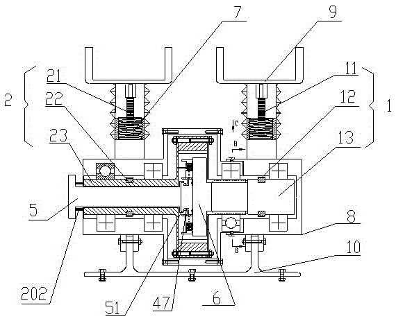
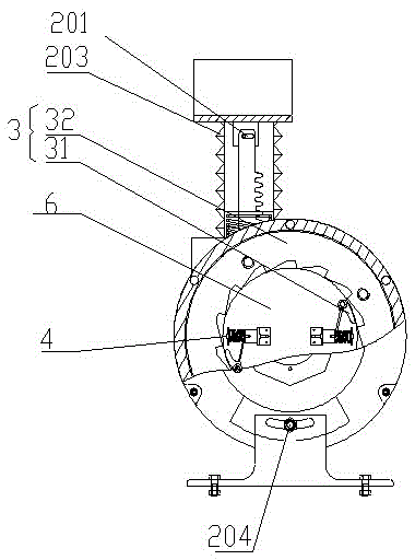
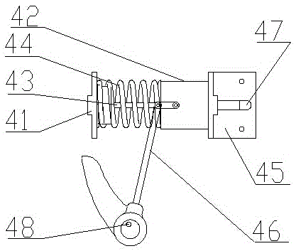
[0032] Such as Figure 1-Figure 7As shown, a mechanical centrifugal vehicle accelerator anti-misstepping safety auxiliary device embodiment of the present invention includes a first rack and pinion mechanism 1 connected under the accelerator pedal of the vehicle, a second rack and pinion mechanism connected under the brake pedal of the vehicle Mechanism 2 and an internal meshing ratchet mechanism 3 that connects the first rack and pinion mechanism 1 and the second rack and pinion mechanism 2 and makes them interlock. The first rack and pinion mechanism 1 includes a first rack 11 and a first gear 12. A gear 12 is mounted on an input shaft 13 as its gear shaft,...


PUM


Abstract

The invention discloses a mechanical centrifugal vehicle accelerator misapplication prevention safety assistance device. The device comprises a first gear and rack mechanism, a second gear and rack mechanism and an internal meshing ratchet wheel mechanism connecting the first gear and rack mechanism and the second gear and rack mechanism. A pawl of the internal meshing ratchet wheel mechanism is connected with a centrifugal push rod mechanism, the pawl and the centrifugal push rod mechanism are arranged at the output end of a gear shaft of the first gear and rack mechanism, a ratchet wheel is arranged at the input end of a gear shaft of the second gear and rack mechanism, the two gear shafts are arranged in a supporting shell through bearings, and two racks are sleeved with return springs. When an accelerator pedal is mistakenly treaded and quickly pressed, the gear shaft of the first gear and rack mechanism is driven by the racks to quickly rotate, the centrifugal push rod mechanism generates centrifugal force to drive the pawl to open and be meshed with the ratchet wheel, and the ratchet wheel drives the gear shaft of the second gear and rack mechanism to rotate so that the racks can drive a brake pedal to be pressed downwards, and braking is achieved. The device is simple in structure, the performance of the original structure is not affected, and the braking performance of the device is safe and reliable.

Description

technical field [0001] The invention relates to the technical field of vehicle safety facilities, in particular to a mechanical centrifugal vehicle accelerator anti-misstepping safety auxiliary device. Background technique [0002] With the continuous increase of motor vehicles, while automobiles bring convenience to human beings, they also bring hidden dangers to public safety, and traffic accidents cause unnecessary losses of human life and property. Since the first traffic accident in which pedestrians and motor vehicles collided and died in 1896, more than 34 million people have died in road traffic accidents all over the world, and more than 500,000 people die in traffic accidents every year, and about 10 million people are injured. The traffic accidents in our country are also increasing year by year with the rapid increase of car ownership. In 2010, a total of 3,906,164 road traffic accidents were reported across the country, including 219,521 road traffic accidents ...

Claims


Application Information

Patent Timeline
IPC IPC(8): B60K26/02B60T7/12
CPCB60K26/02B60T7/12
Inventor 李军政陈昭君杨跃强敏曹瑞玲李满
Owner HUNAN AGRICULTURAL UNIV
Learn More