A device for preventing mistaken use of accelerator as brake

A technology of an accelerator pedal and a brake pedal, which is applied in the field of devices that prevent the accelerator from being mistakenly used as a brake. It can solve the problems of not being able to use the accelerator, difficulty adapting, and not being able to step on the accelerator. It achieves good stability and reliability, and low cost of mechanical structure. The effect of improving comfort

Inactive Publication Date: 2018-10-26
HARBIN UNIV OF SCI & TECH
View PDF6 Cites 0 Cited by
  • Summary
  • Abstract
  • Description
  • Claims
  • Application Information

AI Technical Summary

Problems solved by technology

When an emergency brake is required in a critical situation ahead of the vehicle, the correct operation is to lift the right foot from the accelerator pedal and step on the brake pedal, but some drivers, especially new drivers, may put The accelerator was accidentally stepped on when the brakes were slammed, resulting in a traffic accident that should have been avoided
[0003] In the current literature and patents published on the anti-acceleration system of automobiles, they are mainly divided into three categories: the first category is to change the structure of the existing brake, operate the left and right feet separately, and control the accelerator with one foot and the brake with the other. The disadvantage of this type of device is that in an emergency state, it is still easy to make mistakes in the power of the left and right feet, and it is difficult for people to adapt to the current driving habits; the second type is to detect the depressing speed of the accelerator pedal through an electronic sensor. Stop refueling when the pedaling speed exceeds the normal range
The disadvantage of this type of device is that it does not brake while stopping refueling, and there is still the possibility of accidents when the car continues to move forward; The disadvantage of the method is that the emergency brake cannot be set to be a reasonable distance between the obstacle and the car, because sometimes the car needs to approach the object during driving; when the existing method mistakenly uses the accelerator as the brake, it can only be controlled by linkage Braking and braking cannot make the accelerator return to the idle state. It is equivalent to stepping on the accelerator and stepping on the brake at the same time. The car is still in the state of driving with a large accelerator, which offsets part of the braking force. , due to the function of the retractor, there is a problem that the position of the brake pedal is locked and cannot be lifted
In short, the current various methods have not solved the problem of stepping on the brakes and lifting the accelerator when the accelerator is mistakenly used as a brake. The existing patents only consider the situation of quickly stepping on the accelerator when stepping on the accelerator by mistake, and do not consider quickly lifting the brake. In the case of the pedal, the problem that the brake cannot be retracted and the accelerator cannot be stepped on when the brake is lifted quickly has not been solved.
This is also the main reason why the current automobile manufacturers have not adopted their technical solutions.

Method used


Image

  • A device for preventing mistaken use of accelerator as brake
  • A device for preventing mistaken use of accelerator as brake

Examples


Embodiment 1

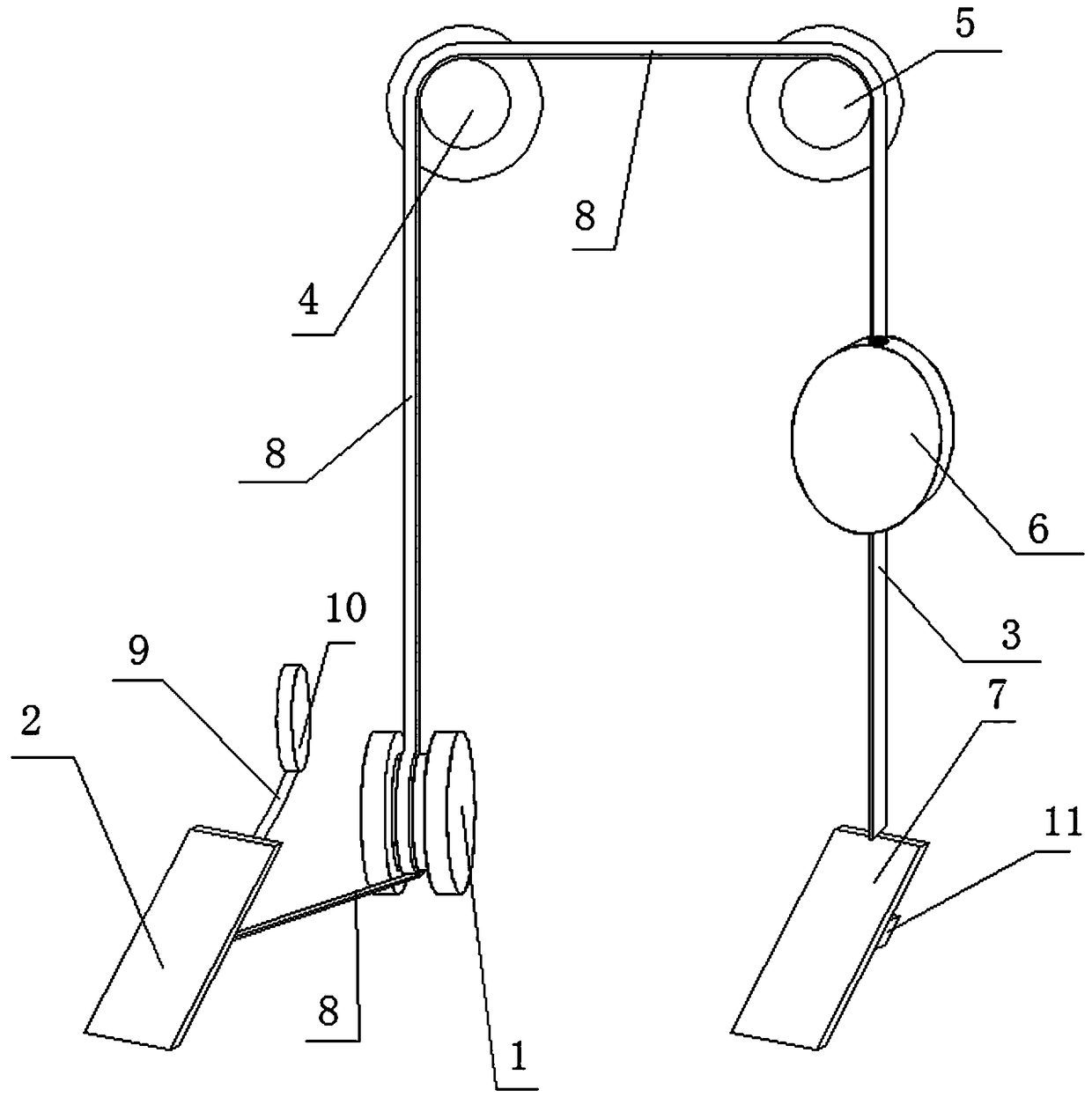
[0019] A device for preventing the gas pedal from being mistakenly used as a brake, which consists of: a car body, the car body includes an accelerator pedal 7, a position sensor 11 is arranged on the accelerator pedal 7, a steel wire rope I3 ​​is connected to the accelerator pedal 7, the The steel wire rope I3 ​​is wound on the inner reel of the retractor 6, and the top of the outer surface of the retractor 6 is fixedly connected to the steel wire rope II8, and the steel wire rope II8 passes through the pulley I5, the pulley II4 and the pulley III1 and then is connected to the brake pedal bracket. The one-way rotation damper 10 is connected to a brake pedal bracket, on which a brake pedal 2 is arranged, and the retractor 6 is arranged between the accelerator pedal 7 and the pulley I5.

[0020] Further, the steel wire rope I3 ​​and the steel wire rope II8 can be replaced with synthetic fiber belts or oil wire ropes.

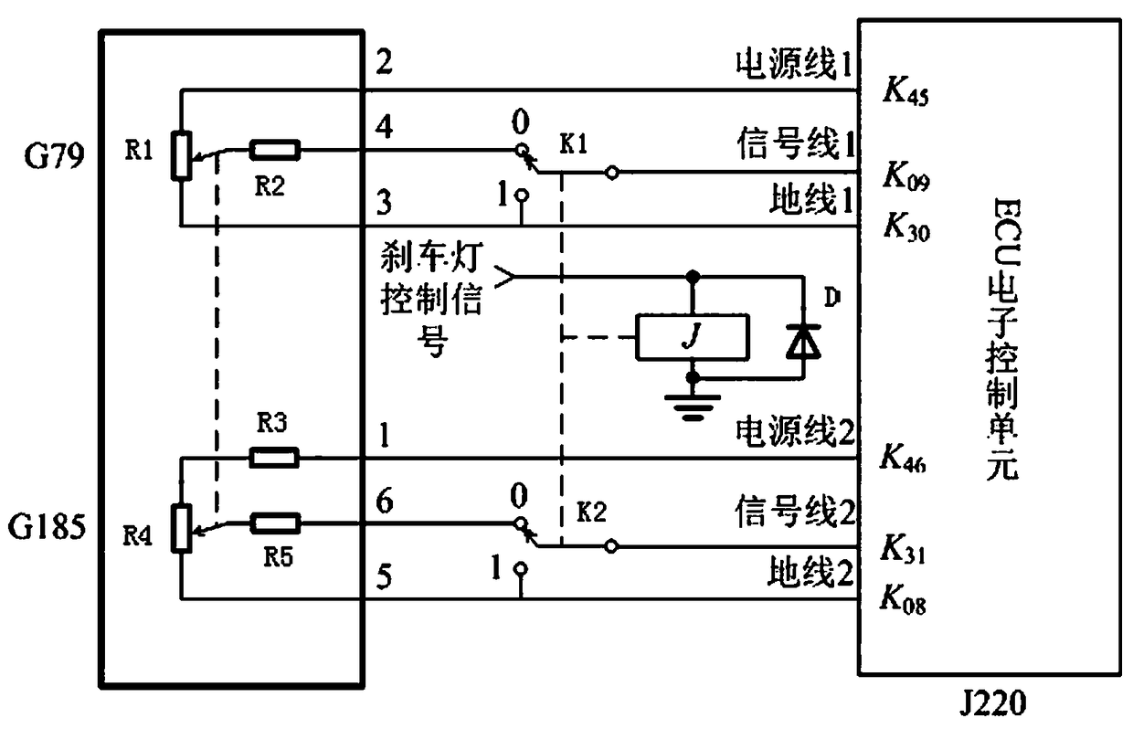
[0021] Further, the K45 pin of the ECU electronic control u...

Embodiment 2

[0029] Embodiment 1 The brake mechanical control part is mainly composed of a one-way rotary damper 10, a retractor 6, a synthetic fiber belt or a steel wire rope (oil wire rope) 3, and three pulleys.

[0030] When neither the accelerator pedal nor the brake pedal is moved, the pre-tightening function of the retractor will shrink the excess synthetic fiber belt or steel wire rope (oil wire rope) into the retractor, so that the synthetic fiber belt or steel wire rope (oil wire rope) ) to tighten.

[0031] When the accelerator pedal moves downwards or upwards at normal speed, that is, the acceleration is lower than 0.8g, the retractor releases the synthetic fiber belt or steel wire rope (oil wire rope) from the retractor outward or retracts it inward;

[0032] When the brake pedal moves down, the retractor winds the synthetic fiber belt or steel wire rope (oil wire rope) inward. When the brake is normally lifted, the retractor releases the synthetic fiber belt or steel wire rop...


PUM


Abstract

The invention provides a device for preventing an accelerator from being mistakenly regarded as a brake and relates to an automotive electronic accelerator and a brake. The problem of throttling back while the accelerator is mistakenly regarded as the brake to cause braking is not solved well by adopting existing various methods, and meanwhile the problem that the brake cannot return and the accelerator cannot be treaded when the brake is about to lift is not considered in existing inventions. The problems are also the main causes that existing automobile production manufacturer do not adopt the technical schemes of the inventions. An automobile body comprises an accelerator pedal, wherein a position sensor is arranged on the accelerator pedal, a steel wire rope I is connected to the accelerator pedal is wound around an internal reel in a winder, a steel wire rope II is fixedly connected to the top end of the outer surface of the winder, penetrates through a pulley I, a pulley II and a pulley III and then is connected to a brake pedal support, a unidirectional rotting damper is connected with the brake pedal support, a brake pedal is arranged on the brake pedal support, and the winder is arranged between the accelerator pedal and the pulley I. The device is used for preventing the accelerator from being mistakenly regarded as the brake.

Description

technical field [0001] The invention relates to a device for preventing an accelerator from being mistakenly used as a brake, and relates to an automobile electronic accelerator and brake. Background technique [0002] With the development of science and technology and the continuous improvement of national life, automobiles are gradually entering every family as one of the main means of transportation. Due to the new non-professional drivers driving on the road, accidents of drivers mistakenly using the accelerator as the brake happen from time to time , has brought great harm to people's lives and property safety. The brake and accelerator of the car are controlled by the right foot, and the position of the brake and the accelerator is very close. When the car needs to speed up in normal driving, the correct way is to step on the accelerator pedal gradually. Car driving experiments have proved that stepping on the accelerator pedal to the bottom cannot instantly increase ...

Claims


Application Information

Patent Timeline
Patent Type & Authority Patents(China)
IPC IPC(8): B60K26/02B60T7/06B60K28/14
CPCB60K26/02B60K28/14B60T7/06
Inventor 吴丽华倪孝深商庆华唐玉仙
Owner HARBIN UNIV OF SCI & TECH
Why Eureka
Try Eureka