Device for recycling waste heat of boiler

A boiler waste heat and boiler technology, applied in heat storage heaters, fluid heaters, lighting and heating equipment, etc., can solve problems such as slow progress

Inactive Publication Date: 2016-05-18
林丽芳
0 Cites 3 Cited by

AI-Extracted Technical Summary

Problems solved by technology

However, technology to reco...

Method used

Boiler 1 is divided into furnace chamber 101 and boiler chamber 103, is provided with heating plate 102 between furnace chamber 101 and boiler chamber 103, is equipped with circulating pipe 2011 by fixed block 1021 on heating plate 102, facilitates heat-absorbing medium to absorb residual heat, one end of the circulation pipe 2011 runs through the heat-absorbing medium inlet 2012 and connect...

Abstract

The invention discloses a device for recycling waste heat of a boiler. The device comprises the boiler and a heating water tank, wherein a water injecting port is formed in the upper part of the heating water tank, a hot water outlet is formed in one side of the heating water tank, the inside of the heating water tank is divided into a large chamber and a small chamber by a separating plate, a circulating pump is fixedly mounted inside the small chamber by the aid of a support, a circulating pipe circles inside the large chamber and fixed in the large chamber by the aid of a support, one end of the circulating pipe penetrates through the separating plate to be connected with a cold medium outlet formed in the circulating pump, the other end of the circulating pipe penetrates through the separating plate to be connected with a cold medium inlet formed in the circulating pump, and a heat absorbing medium inlet and a heat absorbing medium outlet are formed in two ends of one side of the heating water tank. The device for recycling the waste heat of the boiler adopts the circulating pipe and the circulating pump, heat remaining after heating of the boiler is collected and used for heating water in the water tank, the water is supplied to people for use, and the device is environment-friendly, low-carbon and energy-saving.

Application Domain

Storage heaters

Technology Topic

Cold mediumWater tanks +4

Image

  • Device for recycling waste heat of boiler
  • Device for recycling waste heat of boiler
  • Device for recycling waste heat of boiler

Examples

  • Experimental program(1)

Example Embodiment

[0014] The technical solutions in the embodiments of the present invention will be clearly and completely described below in conjunction with the accompanying drawings in the embodiments of the present invention. Obviously, the described embodiments are only a part of the embodiments of the present invention, rather than all the embodiments. Based on the embodiments of the present invention, all other embodiments obtained by those of ordinary skill in the art without creative work shall fall within the protection scope of the present invention.
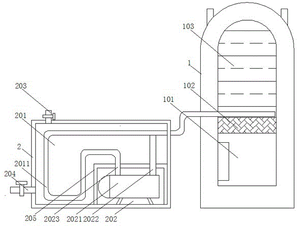
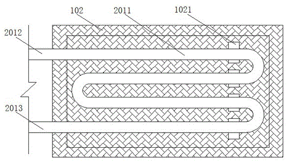
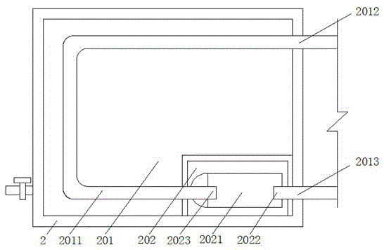
[0015] See Figure 1-3 , The present invention provides a technical solution: a boiler waste heat recovery and utilization device, comprising a boiler 1 and a heating water tank 2. The upper part of the heating water tank 2 is provided with a water injection port 203, and one side of the heating water tank 2 is provided with a hot water outlet 204, which is convenient People use hot water. Valves are installed on the water injection port 203 and the hot water outlet 204. It is not convenient to close. The upper part of the boiler 1 is provided with a water inlet and an exhaust port, and the back of the boiler 1 is provided with a water outlet to heat the water tank 2. The inside is divided into a large chamber 201 and a small chamber 202 by a partition 205. A circulating pump 2021 is fixedly installed in the small chamber 202 through a bracket to circulate the heat-absorbing medium. The large chamber 201 has a circulating pipe circling inside. In 2011, it is convenient for the heat-absorbing medium to circulate and heat between the boiler 1 and the heating water tank 2, and the circulation pipe 2011 is fixed inside the large chamber 201 by a bracket. One end of the circulation pipe 2011 penetrates the partition plate 205 and the cooling set on the circulation pump 2021. The medium outlet 2022 is connected. The other end of the circulating pipe 2011 passes through the partition 205 and is connected to the cold medium inlet 2023 provided on the circulating pump 2021. One end of the heating water tank 2 is provided with a heat absorption medium inlet 2012 and a heat absorption medium outlet 2013. .
[0016] The boiler 1 is divided into a furnace chamber 101 and a boiler chamber 103. A heating plate 102 is arranged between the furnace chamber 101 and the boiler chamber 103. A circulating pipe 2011 is installed on the heating plate 102 through a fixed block 1021 to facilitate the absorption of residual heat by the heat-absorbing medium and circulation One end of the pipe 2011 runs through the heat absorbing medium inlet 2012 and is connected to the cold medium inlet 2023, and the other end of the circulating pipe 2011 passes through the heat absorbing medium outlet 2013 and is connected to the cold medium outlet 2022. The boiler waste heat recovery and utilization device uses the circulating pipe 2011 and circulation. The pump 2021 collects the residual heat after the boiler 1 is heated, and is used to heat the water in the water tank for people to use, which is environmentally friendly, low-carbon and energy-saving.
[0017] Working principle: When the boiler 1 stops working, the circulating pump 2021 is started. After the heat absorption medium in the circulating pipe 2011 starts to absorb a large amount of residual heat on the heating plate 102, it enters the large chamber 201 through the heat absorption medium inlet 2012. The cold water therein is heated, and then enters the circulating pump 2021 through the cold medium inlet 2023, and enters the circulating pipe 2011 on the heating plate 201 from the cold medium outlet 2022 and the heat-absorbing medium outlet 2013 through the circulating pump 2021 for recirculating heating.
[0018] Although the embodiments of the present invention have been shown and described, those of ordinary skill in the art can understand that various changes, modifications, and substitutions can be made to these embodiments without departing from the principle and spirit of the present invention. And variations, the scope of the present invention is defined by the appended claims and their equivalents.

PUM

no PUM

Description & Claims & Application Information

We can also present the details of the Description, Claims and Application information to help users get a comprehensive understanding of the technical details of the patent, such as background art, summary of invention, brief description of drawings, description of embodiments, and other original content. On the other hand, users can also determine the specific scope of protection of the technology through the list of claims; as well as understand the changes in the life cycle of the technology with the presentation of the patent timeline. Login to view more.
Why Eureka
Try Eureka