Thermoelectric conversion module, thermoelectric conversion device, and their manufacturing method

a technology of thermoelectric conversion module and manufacturing method, which is applied in the manufacture/treatment of thermoelectric devices, paper/cardboard containers, generators/motors, etc., can solve the problems of difficulty in achieving sufficient output, and achieve the effect of easy attainment of high voltage outpu

Inactive Publication Date: 2010-07-08
SUMITOMO CHEM CO LTD
View PDF1 Cites 20 Cited by
  • Summary
  • Abstract
  • Description
  • Claims
  • Application Information

AI Technical Summary

Benefits of technology

[0010]It is preferable that thermoelectric conversion devices are electrically serially connected so that high voltage output can be easily attained.
[0011]It is also preferable that thermoelectric conversion devices doubly or multiply enclose the through hole so ...

Problems solved by technology

In conventional arts, however, it has...

Method used


Image

  • Thermoelectric conversion module, thermoelectric conversion device, and their manufacturing method
  • Thermoelectric conversion module, thermoelectric conversion device, and their manufacturing method
  • Thermoelectric conversion module, thermoelectric conversion device, and their manufacturing method

Examples


Embodiment Construction

[0022]The finding of the present invention can be understood easily by considering the following detailed descriptions referring to appended figures shown only for exemplification. Next, embodiments of the present invention will be described referring to appended figures. If possible, the same symbol is used for the same element, and duplicated explanations are omitted.

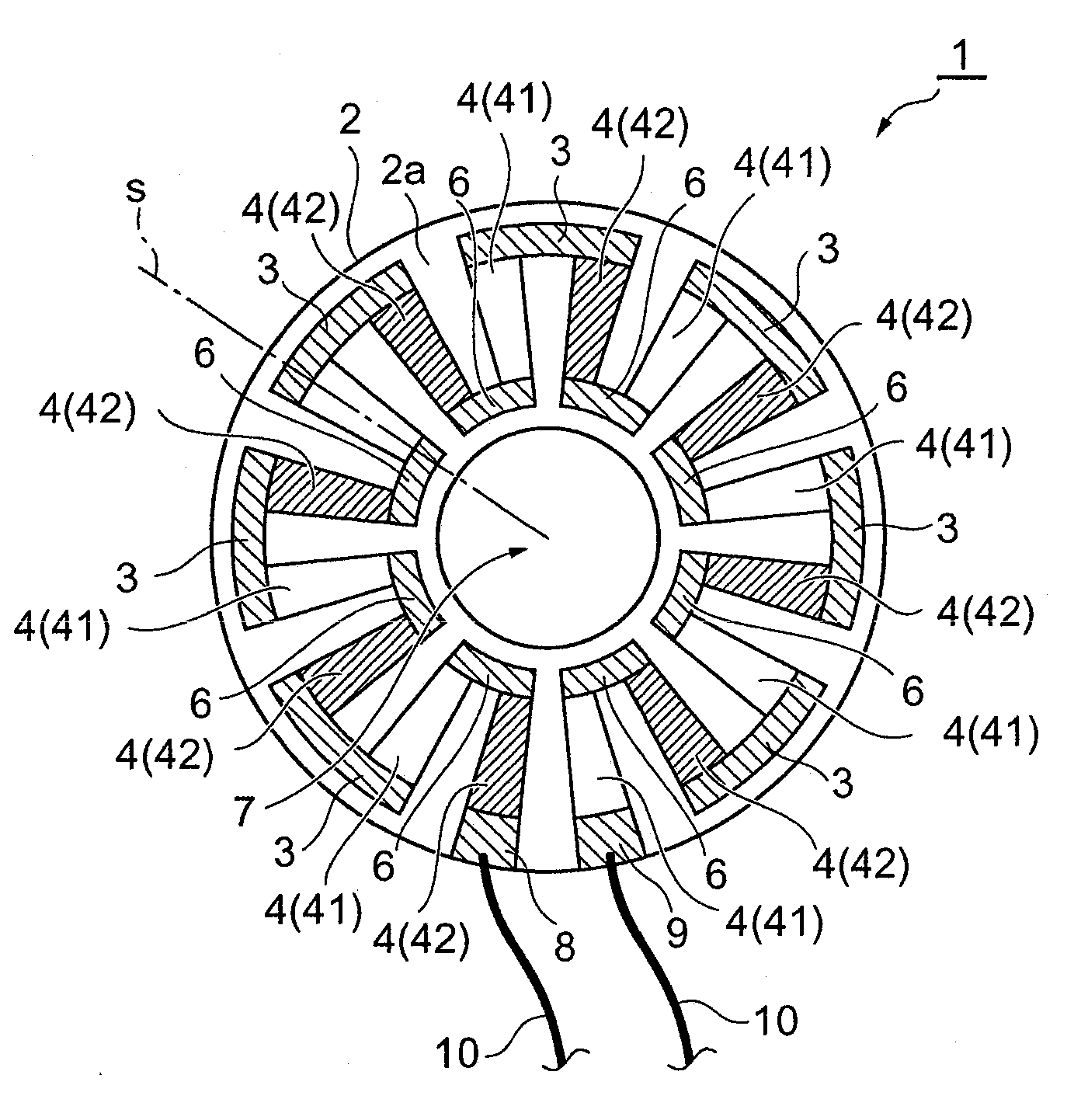
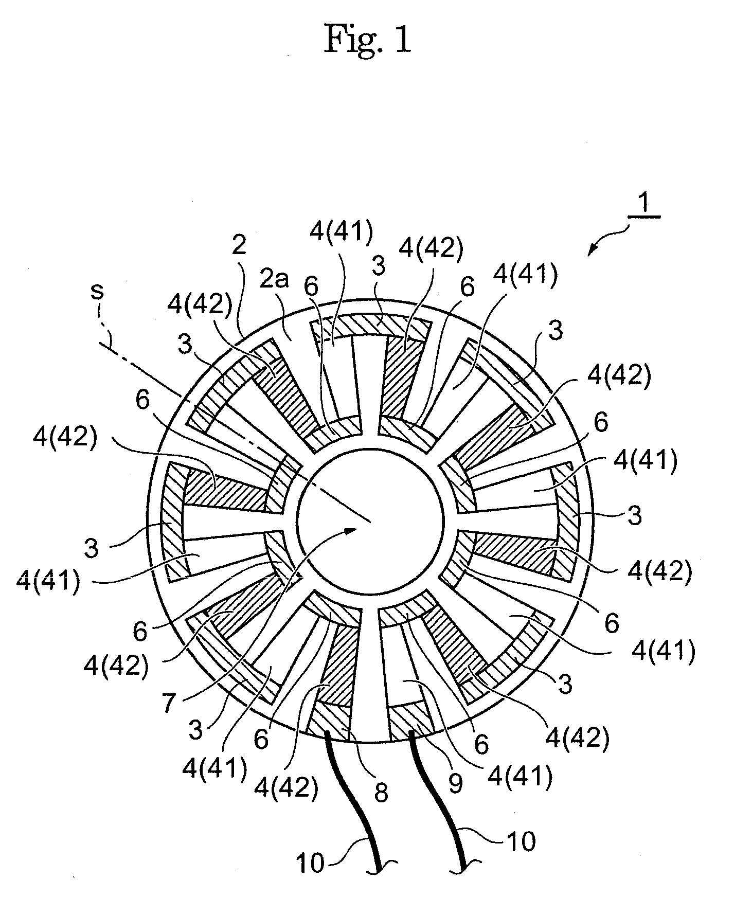
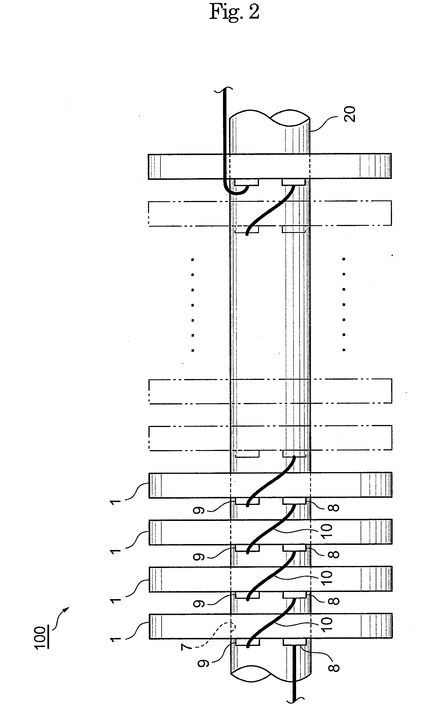
[0023]First, a thermoelectric conversion module 1 of an embodiment of the present invention will be illustrated. As shown in FIG. 1 and FIG. 2, the thermoelectric conversion module 1 has mainly a substrate 2, a plurality of thermoelectric conversion devices 4 on the surface 2a of the substrate 2, and wiring members 3 and 6 for electrically mutually connecting the thermoelectric conversion devices 4 in series.

[0024]The substrate 2 is in the form of circular disk, and has a through hole 7, for example in the form of circle, formed to extend through the surface and the back thereof, around the center position thereof. Th...


PUM

PropertyMeasurementUnit
Electrical conductivityaaaaaaaaaa
Widthaaaaaaaaaa

Abstract

A thermoelectric conversion module includes a substrate and a plurality of thermoelectric conversion devices arranged on the surface of the substrate. The substrate is provided with a through hole formed to extend through the surface and the back thereof, and the thermoelectric conversion devices are arranged on at least one of the surface and the back of the substrate so as to enclose the through hole. The thermoelectric conversion device includes the thermoelectric conversion module, and a tube arranged to extend through the through hole of the thermoelectric conversion module and to allow a hot medium or a cold medium to flow therethrough. A method for manufacturing a thermoelectric conversion module includes a step of arranging a plurality of thermoelectric conversion devices on at least one of the surface and the back of a substrate having a through hole extending through the surface and the back thereof so as to enclose the through hole.

Description

TECHNICAL FIELD[0001]The present invention relates to a thermoelectric conversion module, a thermoelectric conversion unit and their manufacturing method.BACKGROUND ART[0002]As a thermoelectric conversion module for carrying out power generation with a temperature difference between a tube through which a hot medium or cold medium flows and an atmosphere outside of the tube, a thermoelectric conversion module is known having a thermoelectric conversion material coated on the surface and the back of a annular member surrounding a tube and on the side face thereof (for example, JP-A-2006-228852).DISCLOSURE OF THE INVENTION[0003]In conventional arts, however, it has been difficult to attain sufficient output. The present invention has been made to solve the above-described problem and has an object of providing a thermoelectric conversion module with a sufficient output used for a tube, a thermoelectric conversion unit and their manufacturing method.[0004]The thermoelectric conversion ...

Claims


Application Information

Patent Timeline
IPC IPC(8): H01L35/30B29C65/02B29C65/48B05D5/12H01L35/34
CPCH01L35/32H02N11/002Y10T156/10H10N10/17
Inventor HIROYAMA, YUICHINAKANE, KENJI
Owner SUMITOMO CHEM CO LTD
Why Eureka
Try Eureka