Micro-fluidic chip for viscosity testing, and preparation method

A technology of a microfluidic chip and a manufacturing method, which are applied in the process of producing decorative surface effects, the manufacture/assembly of piezoelectric/electrostrictive devices, and measurement devices, etc., can solve the problems affecting material deformation, limited deformation, There are no problems, such as strong operability and simple preparation process.

Active Publication Date: 2016-09-07
HUBEI UNIV
View PDF5 Cites 7 Cited by
  • Summary
  • Abstract
  • Description
  • Claims
  • Application Information

AI Technical Summary

Problems solved by technology

However, the microfluidic chip with this four-layer structure cannot be used for liquid testing with a certain viscosity. The main reasons are: (1) In terms of materials, "Microfluidic chip with self-power supply function and its manufacturing method" (201510304240.5) KNN is used as the piezoelectric material. The rigidity and brittleness of the material are relatively high, and the hard substrate under the material will also affect the deformation of the material. Therefore, the small mechanical energy of the fluid has limited deformation of the material, and the output voltage is small. (only mV level), it is difficult to test the viscosity
(2) Structurally, the piezoelectric material in "Microfluidic Chip with Self-Power Supply Function and Its Fabrication Method" (201510304240.5) is directly expo

Method used


Image

  • Micro-fluidic chip for viscosity testing, and preparation method
  • Micro-fluidic chip for viscosity testing, and preparation method
  • Micro-fluidic chip for viscosity testing, and preparation method

Examples


Example Embodiment

[0079] Example one:

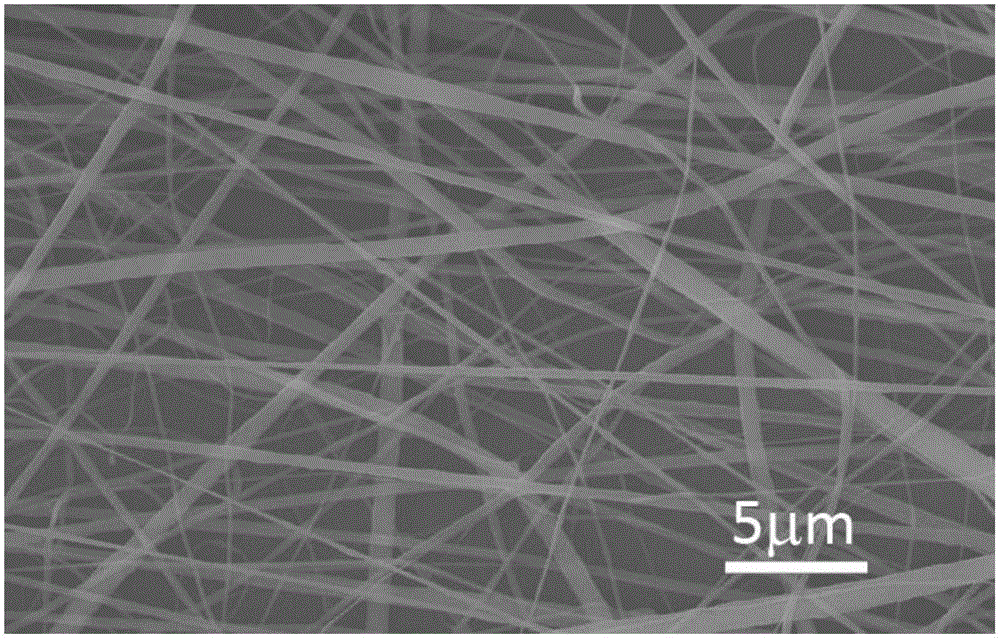
[0080] 1.1 Preparation of PVDF nanofibers by electrospinning

[0081] 1.1.1 The configuration of PVDF precursor solution: mix dimethylformamide (DMF) and acetone in a ratio of 30%:70% by volume and stir evenly; according to the ratio of PVDF concentration of 0.12g / ml Add PVDF powder to the mixture of DMF and acetone, and seal and stir for 60 minutes at 60°C until the entire solution is clear and transparent.

[0082] 1.1.2 Electrospinning: The PVDF precursor prepared in step 1.1.1 is sucked into the syringe, and the syringe is installed on the micro syringe pump, and then the syringe needle is connected to the positive pole of the DC voltage source and attached to the receiving electrode plate. Two pieces of aluminum foil are connected to the negative electrode of the DC voltage source; the direction of the needle is perpendicular to the surface of the receiving plate, the distance between the needle and the receiving plate is 15cm, the voltage of the DC voltag...

Example Embodiment

[0104] Embodiment two:

[0105] 2.1 Preparation of PVDF nanofibers by electrospinning

[0106] 2.1.1 The configuration of PVDF precursor solution: mix dimethylformamide (DMF) and acetone at a volume percentage of 30%:70% and stir evenly; according to the ratio of PVDF concentration of 0.12g / ml Add PVDF powder to the mixture of DMF and acetone, and seal and stir for 60 minutes at 60°C until the entire solution is clear and transparent.

[0107] 2.1.2 Electrospinning: The PVDF precursor prepared in step 2.1.1 is sucked into the syringe, and the syringe is installed on the micro syringe pump, and then the syringe needle is connected to the positive pole of the DC voltage source and attached to the receiving plate. Two pieces of aluminum foil are connected to the negative electrode of the DC voltage source; the direction of the needle is perpendicular to the surface of the receiving plate, the distance between the needle and the receiving plate is 15cm, the voltage of the DC voltage sou...

Example Embodiment

[0129] Embodiment three:

[0130] 3.1 Preparation of PVDF nanofibers by electrospinning

[0131] 3.1.1 The configuration of PVDF precursor solution: mix dimethylformamide (DMF) and acetone in a ratio of 30%:70% by volume and stir evenly; according to the ratio of PVDF concentration of 0.12g / ml Add PVDF powder to the mixture of DMF and acetone, and seal and stir for 60 minutes at 60°C until the entire solution is clear and transparent.

[0132] 3.1.2 Electrospinning: The PVDF precursor prepared in step 3.1.1 is sucked into the syringe, and the syringe is installed on the micro-syringe pump, and then the syringe needle is connected to the positive pole of the DC voltage source and attached to the receiving plate. Two pieces of aluminum foil are connected to the negative electrode of the DC voltage source; the direction of the needle is perpendicular to the surface of the receiving plate, the distance between the needle and the receiving plate is 15cm, the voltage of the DC voltage sou...


PUM

PropertyMeasurementUnit
Lengthaaaaaaaaaa
Widthaaaaaaaaaa

Abstract

The invention discloses a micro-fluidic chip for viscosity testing, and a preparation method. The chip comprises five structures: a PDMS substrate with a miniature groove, detection electrodes, a PVDF nanofiber film, a PDMS film and a PDMS cover plate with a miniature channel. The preparation method comprises the steps: firstly making the substrate with the miniature groove and the PDMS miniature flow channel cover plate through the photoetching of SU8 photoresist and the demoulding technology; secondly making a pair of detection electrodes at two sides of the miniature groove of the PDMS substrate through employing a mask magnetron sputtering method; thirdly transferring the PVDF film, made through employing an electrostatic spinning method, to the electrodes; finally carrying out the bonding of the substrate and the cover plate, and forming a complete micro-fluidic chip. The micro-fluidic chip is stable in structure, facilitates the integration, is small in number of demands for samples, has no requirements for class, is short in testing time, does not need power, and facilitates the extension of a manufactured micro-fluidic chip viscometer to miniaturization even a hand-held type.

Description

technical field [0001] The invention relates to a microfluidic chip for viscosity testing and a manufacturing method thereof, in particular to a manufacturing method of a self-powered viscosity testing microfluidic chip based on piezoelectric power generation effect, which belongs to organic nano functional materials and microfluidic technology field. Background technique [0002] Viscosity is a very important physical parameter of fluid-based dynamic behavior. In many practical applications, the measurement of fluid viscosity is an essential work. For example, the measurement of plasma viscosity in the process of coagulation testing is a very important task. Similarly, in drugs based on protein antibodies and some macromolecular solutions, viscosity is also a very important indicator of such drugs. In addition, some cardiovascular diseases with a high incidence rate in today's society are often caused by changes in blood viscosity due to the high concentration of some mac...

Claims


Application Information

Patent Timeline
IPC IPC(8): H01L41/08H01L41/22B81C1/00G01N33/00
CPCG01N33/00B81C1/00H10N30/1071H10N30/01
Inventor 顾豪爽潘绪敏王钊胡永明
Owner HUBEI UNIV
Why Eureka
Try Eureka