Method and apparatus for calibrating tool on robot flange coordinate system

A flange coordinate system and a calibration method technology are applied in the field of tool calibration method and device on the robot flange coordinate system, which can solve the problems of affecting workpiece processing efficiency, low tool coordinate system calibration efficiency, and complicated calibration operations.

Active Publication Date: 2016-05-18
BEIJING A&E TECH
View PDF5 Cites 16 Cited by
  • Summary
  • Abstract
  • Description
  • Claims
  • Application Information

AI Technical Summary

Problems solved by technology

[0003] In the long-term research and development, the inventor of the present application found that in the four-point calibration method of the prior art, the center point of the tool needs to move from four directions to the calibration reference point, and there are many motion paths to be selected, that is, in the actual calibration operation process, each The calibration of the tool center requires at least four operations of moving the tool center point to the calibration reference point. The calibration operation is cumbersome and makes the calibration efficiency of the tool coordinate system low, which in turn affects the processing efficiency of the workpiece.

Method used


Image

  • Method and apparatus for calibrating tool on robot flange coordinate system
  • Method and apparatus for calibrating tool on robot flange coordinate system
  • Method and apparatus for calibrating tool on robot flange coordinate system

Examples


Embodiment approach

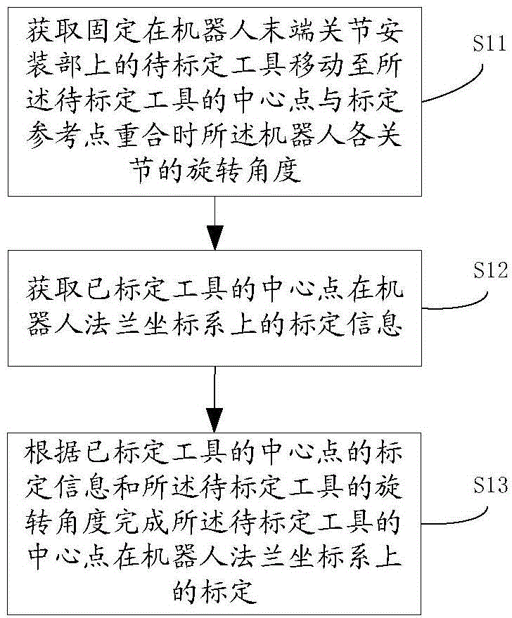
[0072] see figure 1 , an embodiment of the calibration method of the tool on the robot flange coordinate system of the present invention includes:

[0073] Step S11: Obtain the rotation angle of each joint of the robot when the tool to be calibrated fixed on the mounting part of the end joint of the robot moves to the point where the center point of the tool to be calibrated coincides with the calibration reference point.

[0074] In this embodiment, the robot is generally an industrial robot with no less than four joints, preferably an industrial robot with six joints. In other implementation manners, the robot may also be other types of robots such as a primary intelligent robot with no less than four joints, and there is no excessive limitation here.

[0075]After the tool to be calibrated is fixed on the mounting part of the end joint of the robot, the tool to be calibrated is moved so that the center point of the tool to be calibrated coincides with the calibration refer...


PUM


Abstract

The invention discloses a method and apparatus for calibrating a tool on a robot flange coordinate system. The method for calibrating the tool in the robot flange coordinate system comprises the following steps: obtaining a rotation angle of each joint when a tool to be calibrated fixed at a robot tail-end joint installation portion moves until the center point of the tool to be calibrated is superposed with a calibration reference point; obtaining calibration information of the center point of an already calibrated tool on the robot flange coordinate system; and according to the calibration information of the center point of the calibrated tool and the rotation angles of the tool to be calibrated, completing calibration of the center point of the tool to be calibrated on the robot flange coordinate system. According to the invention, the needed tool center point movement path quantity can be reduced, the calibration operation is quite simple, and the calibration efficiency of a tool coordinate system is enabled to be quite high.

Description

technical field [0001] The invention relates to the field of robots, in particular to a calibration method and device for a tool on a robot flange coordinate system. Background technique [0002] In robot programming, it is usually necessary to define the operation task of the workpiece in a coordinate system such as the flange coordinate system of the robot. Therefore, it is necessary to determine in advance the tool coordinate system fixed on the tool and the end joint of the fixed tool before processing the workpiece. The relationship of the flange coordinate system where it is located is to calibrate the tool coordinate system. The calibration of the tool coordinate system is to determine the coordinates of the tool center point in the flange coordinate system and the coordinate axis direction of the tool coordinate system relative to the flange coordinate system. Among them, in the calibration process of the tool coordinate system, the prior art usually adopts a four-po...

Claims


Application Information

Patent Timeline
IPC IPC(8): G01B21/00
CPCB25J9/1692G05B2219/39019G05B2219/39026G05B2219/50291G01B5/004B23Q17/22G01B21/042G01B21/047
Inventor 穆文锋
Owner BEIJING A&E TECH
Why Eureka
Try Eureka