Light-sensitive SMT detecting assembly

A technology for detecting components and patches, which is applied in the direction of measuring devices, material analysis through optical means, instruments, etc., can solve the problems of low detection efficiency of stencil templates, etc., and achieve the effect of reducing the workload of workers and reducing the error rate of inspection

Inactive Publication Date: 2016-05-18
TIANJIN HUAMAI TECH
View PDF11 Cites 5 Cited by
  • Summary
  • Abstract
  • Description
  • Claims
  • Application Information

AI Technical Summary

Problems solved by technology

[0004] The technical problem to be solved by the present invention is: in order to solve the problems existing in the above-mentioned background...

Method used


Image

  • Light-sensitive SMT detecting assembly
  • Light-sensitive SMT detecting assembly

Examples


Embodiment 1

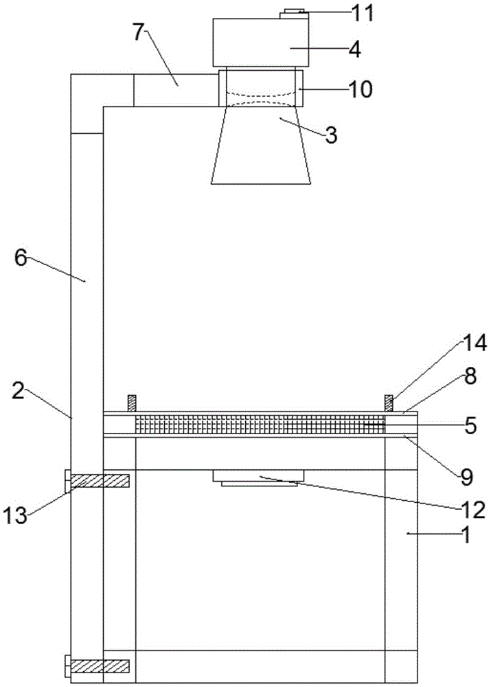
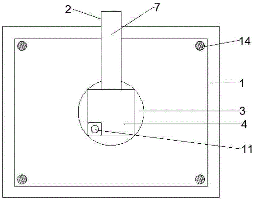
[0019] Embodiment 1: During inspection, a light-sensitive patch detection assembly includes a base 1, a bracket 2, a light source 4, a lens 3 and a photosensitive device 5, the bracket 2 includes a vertical bracket 6 and a horizontal bracket 7, and the top of the vertical bracket 6 is fixed Connect the horizontal bracket 7, the other end of the horizontal bracket 7 is fixedly connected to the lens holder 10, the lens holder 10 is fixedly provided with a lens 3, the upper surface of the lens 3 is fixedly provided with a light source 4, and the upper surface of the light source 4 is fixedly provided with a switch for controlling the light source 4 Device 11, the bottom end of the vertical support 6 is fixedly connected to the side wall of the base 1, the base 1 is a cuboid structure, the upper surface of the base 1 is respectively provided with a first loading platform 8 and a second loading platform 9, and the first loading platform 8 is located on Above the second stage 9, the ...

Embodiment 2

[0022] Embodiment 2: When not in use, a light-sensitive patch detection assembly includes a base 1, a bracket 2, a light source 4, a lens 3 and a photosensitive device 5, the bracket 2 includes a vertical bracket 6 and a horizontal bracket 7, and the top of the vertical bracket 6 Fixedly connected to the horizontal bracket 7, the other end of the horizontal bracket 7 is fixedly connected to the lens holder 10, the lens holder 10 is fixedly provided with a lens 3, the upper surface of the lens 3 is fixedly provided with a light source 4, and the upper surface of the light source 4 is fixedly provided with a control light source 4 The switch device 11, the bottom end of the vertical support 6 is fixedly connected to the side wall of the base 1, the base 1 is a cuboid structure, the upper surface of the base 1 is respectively provided with a first loading platform 8 and a second loading platform 9, the first loading platform 8 Located above the second stage 9, the first stage 8 is...


PUM


Abstract

The invention relates to the technical field of SMT printing steel mesh appearance detection, in particular to a light-sensitive SMT detecting assembly. The light-sensitive SMT detecting assembly comprises a base, a support, a light source, a lens and a light sensing device. The top end of a vertical support body is fixedly connected with a transverse support body, and the other end of the transverse support body is fixedly connected with a lens holder. The light source is fixedly arranged on the upper surface of the lens, the bottom end of the vertical support body is fixedly connected to the side wall of the base, a first object table is a transparent device, the light sensing device is fixedly arranged on the upper surface of a second object table, a plurality of locating devices are fixedly arranged on the upper surface of the first object table, and an alarm is fixedly arranged below the second object table. A steel mesh and filler parts corresponding to holes of the steel mesh are placed on the first object table to form a light-tight layer, the steel mesh is tested through light irradiation of the light source and induction of the light sensing device on light, the workloads of workers are reduced, and meanwhile the test error rate is reduced.

Description

technical field [0001] The invention relates to the technical field of SMT printing steel mesh appearance inspection, in particular to a light-sensitive patch detection component. Background technique [0002] SMT is Surface Mount Technology (Surface Mount Technology) (abbreviation of Surface Mounted Technology), which is currently the most popular technology and process in the electronics assembly industry. SMT is an important link in the supply chain of the electronics manufacturing industry. The SMT printing stencil is a flat mold that must be used in the missing printing solder paste or dispensing process, and the SMT printing stencil is generally a steel mesh. SMT stencil manufacturing is an essential key process in the solder paste printing process, which directly affects the quality of the solder paste printing and is related to the quality of the entire SMT process. 70% of SMT quality problems are related to the printing of solder paste, and 35% of the defects are ...

Claims


Application Information

Patent Timeline
IPC IPC(8): G01N21/956
CPCG01N21/956G01N2021/95638
Inventor 马玉刚
Owner TIANJIN HUAMAI TECH
Why Eureka
Try Eureka