Supercharge Your Innovation With Domain-Expert AI Agents!

Coil forming mold

A coil forming and mold technology, applied in coil manufacturing and other directions, can solve problems such as easy stepping on by mistake, work accidents, etc., achieve the effect of convenient placement and removal, and prevent work accidents

Inactive Publication Date: 2016-05-18
余姚市朗霞镇大众铸件精工厂
View PDF0 Cites 2 Cited by
  • Summary
  • Abstract
  • Description
  • Claims
  • Application Information

AI Technical Summary

Problems solved by technology

Because the lower mold in the previous coil forming mold cannot be moved, the staff needs to reach between the upper mold and the lower mold to put the coil in or take it out, and then the worker steps on the controller to control the mold work, which is very easy to step on by mistake. cause industrial accident

Method used


Image

  • Coil forming mold
  • Coil forming mold
  • Coil forming mold

Examples


Embodiment Construction

[0013] The present invention will be further described in detail below in conjunction with the accompanying drawings and specific embodiments.

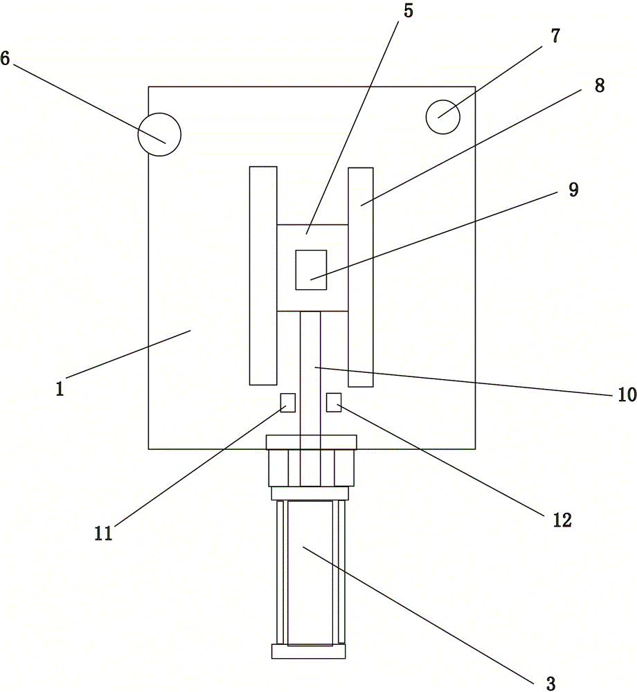
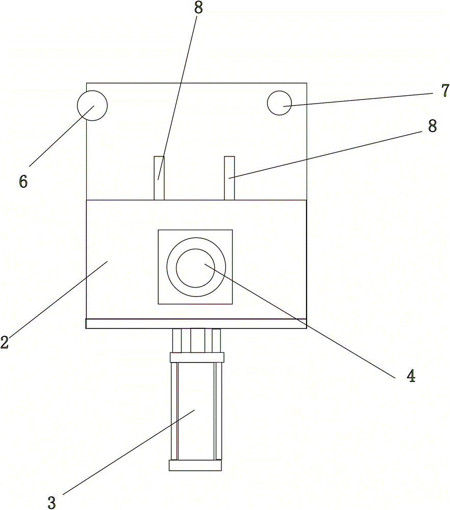
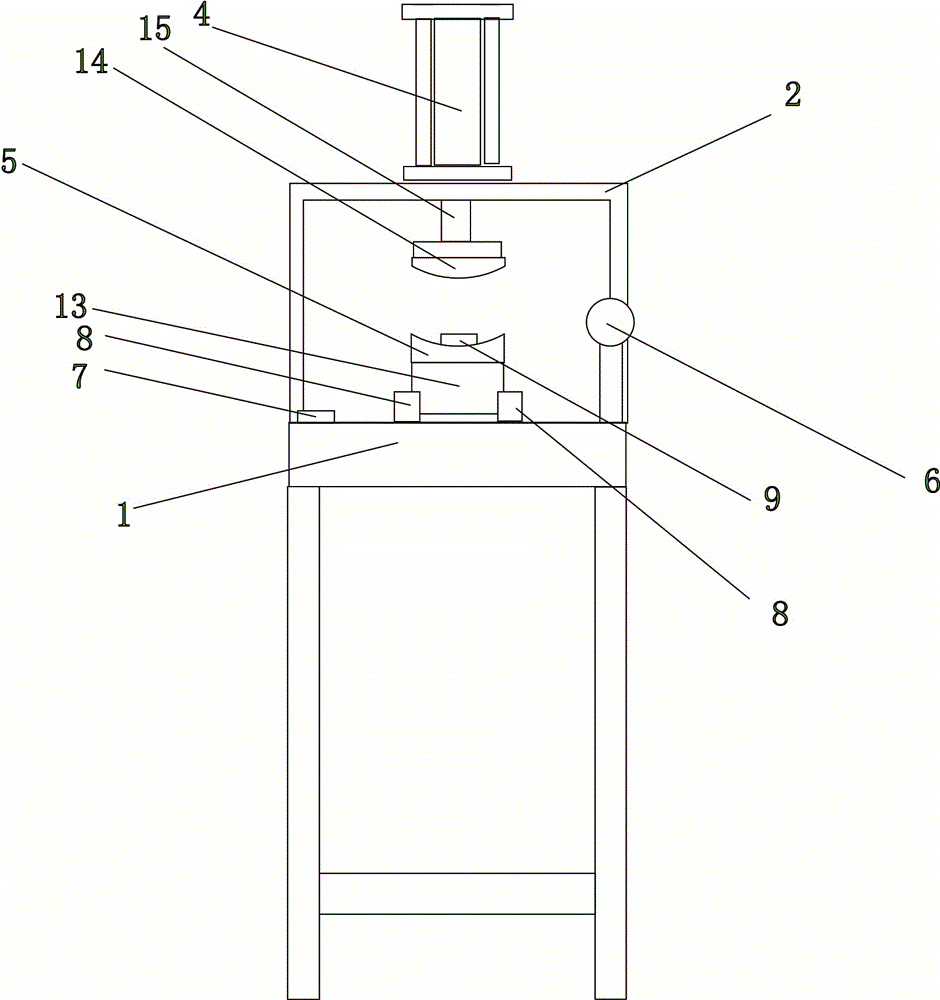
[0014] see Figure 1 to Figure 5 Shown: a coil forming mold, including a working board 1, a support frame 2, a control rod 6, and a power button 7. The support frame 2 is provided with an impact cylinder 4, and the first piston 15 on the impact cylinder 4 is connected with an upper mold 14. The work plate 1 is provided with a slideway 8, and the slideway 8 is provided with a workbench 13 that can slide on the slideway 8, and the slideway 8 extends to just below the upper mold 14. A lower mold 5 is arranged on the workbench 13, and an opening is arranged on the lower mold 5. A spring is arranged in the workbench 13, and a bump 9 passing through the opening of the lower mold 5 is connected on the spring. Working plate 1 limit is provided with moving cylinder 3, and moving cylinder 3 comprises second piston 10, and piston 10 is connect...


PUM


Abstract

The invention provides a coil forming mold, belongs to the field of vehicle engine coil forming molds. The forming mold comprises a working plate, a supporting frame, a control rod, and a power rod. The working plate is provided with a workbench. The supporting frame is provided with an impact cylinder. A detachable upper die is connected under the impact cylinder. The workbench is provided with a lower die which is cooperated with the upper die and is detachable. The workbench is connected with a moving cylinder. The working plate is provided with a first stroke button and a second stroke button. The first stroke button and the second stroke button are in front of the moving cylinder. A coil can be conveniently placed and taken out from the forming mold, and accidents at work caused by misoperation of working personnel are prevented.

Description

technical field [0001] The invention relates to a mold, in particular to an automobile starter coil forming mold. Background technique [0002] The coil is one of the important parts of the car starter. In the car starter, several coils are welded together to form a ring-shaped magnetic field winding that matches the armature in the starter. At this time, each coil must be bent to form a certain arc to closely match the armature. The coil is in the shape of a flat plate when it is first manufactured. At this time, a coil forming die is needed to press the coil into the required arc shape. In the past, the lower mold of the coil forming mold is fixed, and the upper mold is pressed down to press the coil placed on the lower mold into an arc shape. Because the lower mold in the previous coil forming mold cannot be moved, the staff needs to reach between the upper mold and the lower mold to put the coil in or take it out, and then the worker steps on the controller to control ...

Claims


Application Information

Patent Timeline
IPC IPC(8): H01F41/04B21F1/00
Inventor 童均苗
Owner 余姚市朗霞镇大众铸件精工厂
Features
  • R&D
  • Intellectual Property
  • Life Sciences
  • Materials
  • Tech Scout
  • Unparalleled Data Quality
  • Higher Quality Content
  • 60% Fewer Hallucinations
Learn More