Eureka AIR delivers breakthrough ideas for toughest innovation challenges, trusted by R&D personnel around the world.

Klystron base

A technology of klystrons and tube holders, which is applied in the direction of discharge tubes, shells/containers of time-of-flight electron tubes, time-of-flight electron tubes, etc., and can solve the problem of cooling, placement of klystrons and magnets, and connection with power supplies Problems that cannot be solved quickly and conveniently

Active Publication Date: 2016-05-18
SOUTHWESTERN INST OF PHYSICS
View PDF7 Cites 2 Cited by
  • Summary
  • Abstract
  • Description
  • Claims
  • Application Information

AI Technical Summary

Problems solved by technology

[0003] The technical problem solved by the present invention is the problem that the cooling, placement and connection with the power supply of the klystron and the magnet in the prior art cannot be solved conveniently and quickly, and further provides a method that can ensure the placement, connection, and maintenance of the klystron and the magnet. Cooled Klystron Base

Method used


Image

  • Klystron base
  • Klystron base
  • Klystron base

Examples


Embodiment Construction

[0024] The technical solutions and beneficial effects of the present invention will be further described below in conjunction with the accompanying drawings and specific embodiments.

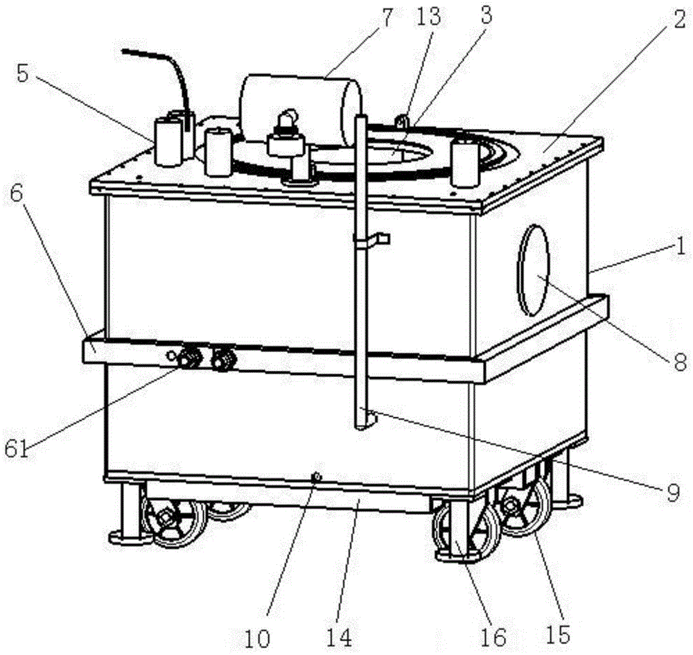
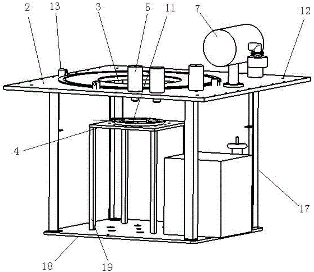
[0025] See attached figure 2 to attach Figure 5 , the klystron socket of the present invention includes an oil tank 1 for accommodating cooling oil, a top plate 2 is installed in a detachable seal on the top of the oil tank 1, and the end of the anode and cathode of the klystron 100 on the top plate 2 passes through Thereby the through hole 3 immersed in the cooling oil, the side wall of the through hole 3 can support the magnet 200 matched with the klystron 100, and the position of the anode after the klystron 100 is inserted into the oil tank 1 at the bottom of the top plate 2 is fixedly connected with the top plate 2 A klystron anode connector 4 is provided, and the position of the cathode corresponding to the klystron 100 inserted into the fuel tank 1 is fixedly connected to the top plate...


PUM


Abstract

Disclosed in the invention is a klystron base comprising an oil tank for accommodating coolant oil. A top plate is installed at the top of the oil tank detachably in a sealing mode; a through hole is formed in the top plate, wherein anode and cathode ends of a klystron pass through the through hole and are immersed into the coolant oil; and the side wall of the through hole can support a magnet cooperating with the klystron. A klystron anode connector fixedly connected with the top plate is arranged at a position, corresponding to the location of the anode of the klystron inserted into the oil tank, of the bottom of the top plate and a cathode connector fixedly connected with the top plate is arranged at a position, corresponding to location of the cathode of the klystron inserted into the oil tank, of the bottom of the top plate. More than two high-voltage wire insulating holes are formed in the top of the top plate. In addition, the klystron base also includes a cooling system for cooling the coolant oil in the oil tank. And a lifting structure and a positioning structure for limiting the radial movement of the magnet are arranged at the top of the top plate. With the klystron base, problems of placing, cooling and connection of a klystron and a magnet can be solved conveniently and rapidly.

Description

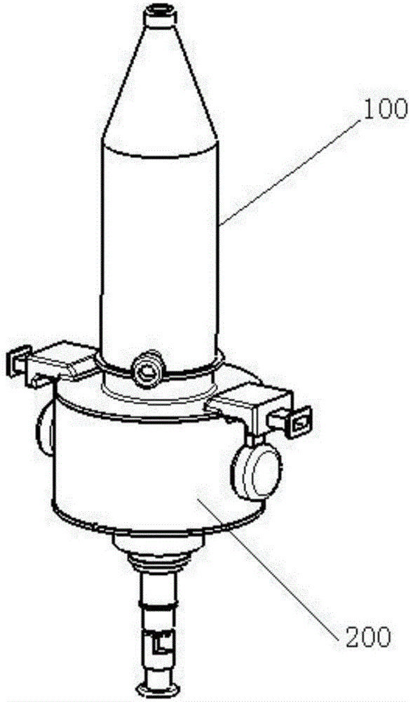
technical field [0001] The invention relates to the field of radio frequency wave auxiliary heating, in particular to a klystron tube base. Background technique [0002] The klystron is a device that generates high-power microwaves in the radio frequency wave heating system. Its working principle is to use the filament to heat the cathode to emit electron beams. High power microwave output. when working, such as figure 1 As shown, the klystron 100 is spaced through the cylindrical magnetic field at the center of the magnet 200 . In order to ensure that the klystron can work stably, it is necessary to ensure that the klystron and the magnet are placed securely, the connection between the klystron and the magnet and the power supply is reliable, and the end where the cathode and anode of the klystron are located is well cooled. This device can solve these problems quickly and easily. Contents of the invention [0003] The technical problem solved by the present invention...

Claims


Application Information

Patent Timeline
Patent Type & Authority Applications(China)
IPC IPC(8): H01J23/00H01J23/12H01J23/033
Inventor 梁军卢波郑铁流
Owner SOUTHWESTERN INST OF PHYSICS
Why Eureka
Eureka Blog
Learn More