
Cavity filter and frequency modulation screw rod structure thereof

A cavity filter and cavity filter technology, which is applied in waveguide devices, resonators, circuits, etc., can solve the problems of limited frequency adjustment range, large screw length range, and operator inconvenience, so as to reduce screw types, The effect of reducing debugging operations and simplifying the structure

Active Publication Date: 2016-05-18
SHENZHEN SAMSUNG COMM TECH RES +1
View PDF3 Cites 4 Cited by
  • Summary
  • Abstract
  • Description
  • Claims
  • Application Information

AI Technical Summary

Problems solved by technology

[0003] 1. Due to the poor sensitivity of this adjustment method and the requirement of a large screw length range, the frequency adjustment range is limited;
[0004] 2. It is often necessary to replace screws of different lengths, which brings inconvenience to the operator

Method used


Image

  • Cavity filter and frequency modulation screw rod structure thereof
  • Cavity filter and frequency modulation screw rod structure thereof
  • Cavity filter and frequency modulation screw rod structure thereof

Examples


Embodiment Construction

[0025] The following will clearly and completely describe the technical solutions in the embodiments of the present invention with reference to the accompanying drawings in the embodiments of the present invention. Obviously, the described embodiments are only some, not all, embodiments of the present invention. Based on the embodiments of the present invention, all other embodiments obtained by persons of ordinary skill in the art without creative efforts fall within the protection scope of the present invention.

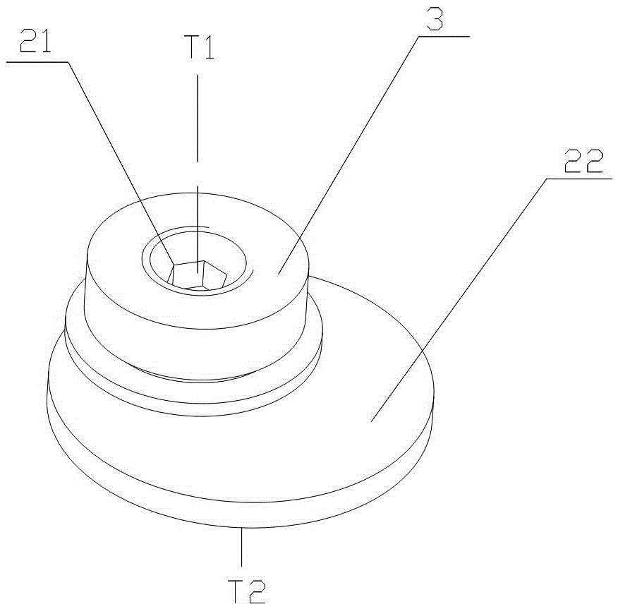
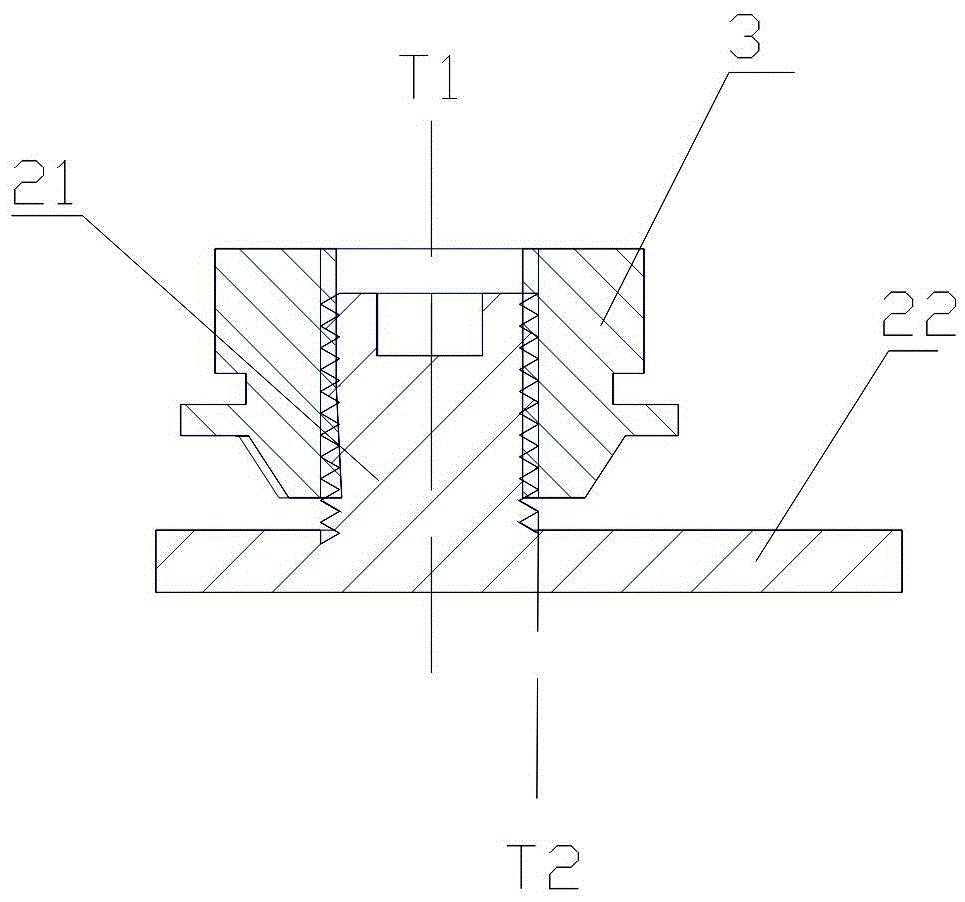
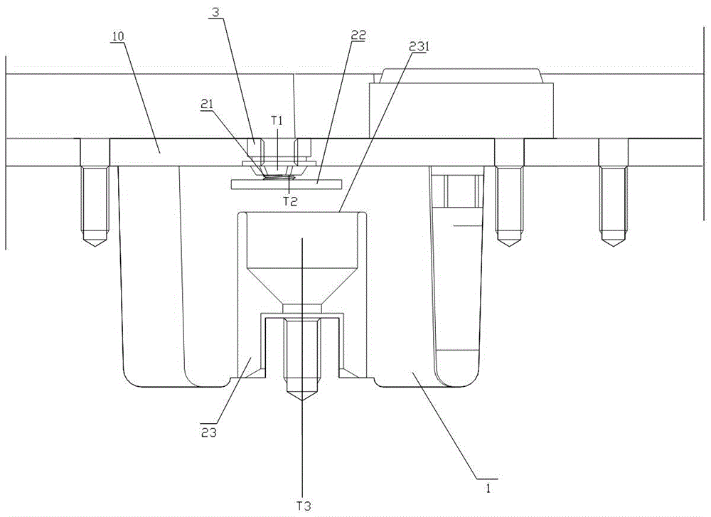
[0026] see in conjunction Figure 1-Figure 3 Shown is Embodiment 1 of the cavity filter of the present invention.

[0027] The cavity filter in this embodiment includes a cavity (the cavity structure formed by the cover plate 1 and other components of the cavity filter), a cover plate 10 that covers the cavity, and a cover that can pass through the cover. Plate 10 and the FM screw structure extending into the cavity, the FM screw structure includes: threaded rod 2...


PUM


Abstract

The invention discloses a frequency modulation screw rod structure used for a cavity filter. The frequency modulation screw rod structure can be disposed on the cover plate of the cavity filter, and is fixedly connected with the cover plate of the cavity filter, and comprises a screw rod; a coupling disc connected with the screw rod; and a resonant rod, which can be fixedly disposed in the housing of the cavity filter. The axis of the screw rod is parallel to the axis of the coupling disc, and a certain distance is arranged between the axis of the screw rod and the axis of the coupling disc. The invention also discloses the cavity filter. By adopting the cavity filter and the frequency modulation screw rod structure thereof, the debugging operation can be reduced, and the screw types can be reduced; the adjusting range can be increased, and the filter debugging efficiency can be increased.

Description

technical field [0001] The invention relates to the field of communication equipment, in particular to a cavity filter and its frequency modulation screw structure. Background technique [0002] The traditional frequency modulation screw structure used in the cavity filter of communication equipment is usually to adjust the capacitive coupling value between the cover plate and the resonant rod by adjusting the length of the deep cavity to achieve the purpose of frequency adjustment. Due to unreasonable design, there are the following technical defects: [0003] 1. Due to the poor sensitivity of this adjustment method and the requirement of a large screw length range, the frequency adjustment range is limited; [0004] 2. It is often necessary to replace screw rods of different lengths, which brings inconvenience to the operator. Contents of the invention [0005] The technical problem to be solved by the present invention is to provide a cavity filter and its frequency m...

Claims


Application Information

Patent Timeline
Patent Type & Authority Applications(China)
IPC IPC(8): H01P1/207H01P7/00
CPCH01P1/207H01P7/00
Inventor 高飞赵广鑫
Owner SHENZHEN SAMSUNG COMM TECH RES
Learn More