Eureka AIR delivers breakthrough ideas for toughest innovation challenges, trusted by R&D personnel around the world.

Taper magnetic bearing switched reluctance motor and control method thereof

A technology of switched reluctance motor and reluctance motor, which is applied in the direction of electrical components, holding devices with magnetic attraction or thrust, etc.

Active Publication Date: 2016-05-18
NANJING UNIV OF POSTS & TELECOMM
View PDF5 Cites 18 Cited by
  • Summary
  • Abstract
  • Description
  • Claims
  • Application Information

AI Technical Summary

Problems solved by technology

From the above three composition forms, it can be seen that the bearingless motor needs to cooperate with at least one axial magnetic bearing to form a five-degree-of-freedom magnetic levitation system, which is also the technical bottleneck of the bearingless motor

Method used


Image

  • Taper magnetic bearing switched reluctance motor and control method thereof
  • Taper magnetic bearing switched reluctance motor and control method thereof
  • Taper magnetic bearing switched reluctance motor and control method thereof

Examples


Embodiment Construction

[0082] The technical scheme of a tapered magnetic bearing switched reluctance motor and its control method of the present invention will be described in detail below in conjunction with the accompanying drawings:

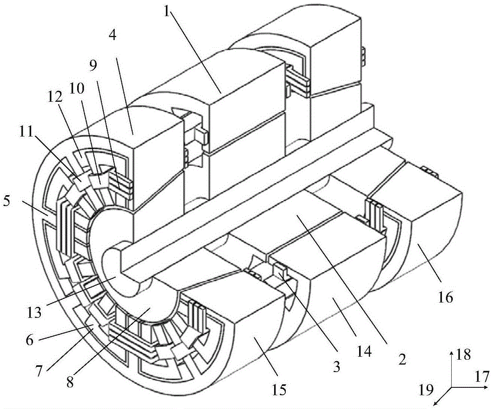
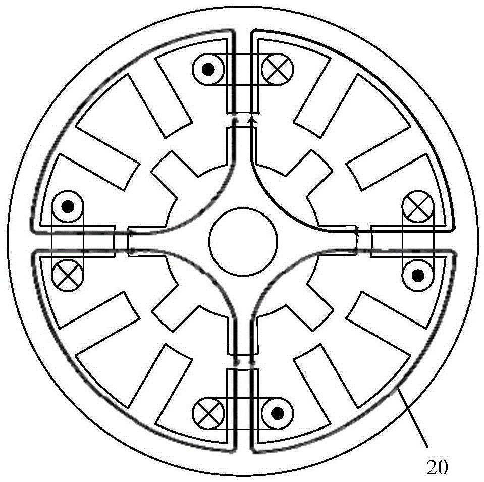
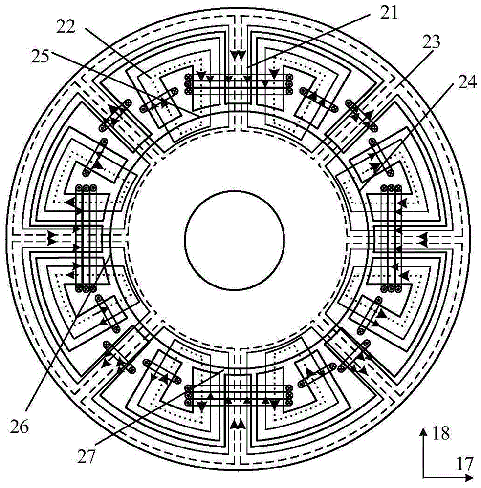
[0083] Such as figure 1 Shown is a three-dimensional structural schematic diagram of embodiment 1 of the tapered magnetic bearing switched reluctance motor of the present invention, wherein, 1 is the stator of the reluctance motor, 2 is the rotor of the reluctance motor, 3 is the winding of the reluctance motor, and 4 is the tapered stator , 5 is axial force stator, 6 is radial force stator, 7 is C-shaped structure, 8 is conical rotor, 9 is bias winding, 10 is radial suspension winding, 11 is axial suspension winding, 12 is non-conductive Magnetic components, 13 is a rotating shaft, 14 is a 12 / 8-pole switched reluctance motor, 15 is a tapered magnetic bearing I, and 16 is a tapered magnetic bearing II.

[0084] The tapered magnetic bearing switched reluctance motor...


PUM


Abstract

The present invention discloses a taper magnetic bearing switched reluctance motor and a control method thereof. The motor is composed of a switched reluctance motor and two taper magnetic bearings; the bias windings of the two taper magnetic bearings are connected in series with the winding of the switched reluctance motor to a form m-phase torque winding; two vertical suspension windings of each taper magnetic bearing are configured to control the suspension with two degrees of freedom, have four vertical degrees of freedom and are able to perform decoupling control; the axial suspension windings of the two taper magnetic bearings are connected in series to form an axial suspension winding for controlling the axial suspension; the motor is able to independently control the opening and closing angles of a torque winding current and power circuit to control the rotating speed and the torque in real time; and the motor is able to control five suspension winding currents to regulate the suspension forces in five directions so as to realize the suspension with five degrees of freedom. The taper magnetic bearing switched reluctance motor and the control method thereof are small in control variables, simple in suspension control and low in cost of a suspension system power converter.

Description

technical field [0001] The invention relates to a tapered magnetic bearing switched reluctance motor and a control method, belonging to the technical field of magnetic levitation switched reluctance motors and their control. Background technique [0002] The bearingless switched reluctance motor is a new type of magnetic levitation motor developed in the 1990s. Since the bearingless switched reluctance motor integrates the functions of rotation and suspension, it can not only effectively solve the problems of loss and heat caused by bearing friction during high-speed operation, but also further exert the high-speed adaptability of the switched reluctance motor, thereby strengthening its Application base in high-speed fields such as aerospace, flywheel energy storage, and ships. [0003] The study found that whether the rotation and levitation functions of the bearingless switched reluctance motor can be decoupled, as well as the tracking and chopping control accuracy of the...

Claims


Application Information

Patent Timeline
Patent Type & Authority Applications(China)
IPC IPC(8): H02N15/00
CPCH02N15/00
Inventor 刘泽远杨艳曹鑫邓智泉王世山
Owner NANJING UNIV OF POSTS & TELECOMM
Why Eureka
Eureka Blog
Learn More