Supercharge Your Innovation With Domain-Expert AI Agents!

Constant-velocity universal joint

A technology of constant velocity universal joints and inner joints, which is applied in the direction of anti-centrifugal rotating parts, elastic couplings, mechanical equipment, etc., can solve problems such as energy loss, achieve the effects of preventing locking and improving energy transfer efficiency

Active Publication Date: 2016-05-18
ERAE AMS CO LTD
View PDF8 Cites 0 Cited by
  • Summary
  • Abstract
  • Description
  • Claims
  • Application Information

AI Technical Summary

Problems solved by technology

[0005] However, in constant velocity universal joints with large joint angles, joints with O / H ratio values ​​in this range have huge energy losses

Method used


Image

  • Constant-velocity universal joint
  • Constant-velocity universal joint
  • Constant-velocity universal joint

Examples


Embodiment Construction

[0025] The embodiments of the present invention will be described in detail below with reference to the accompanying drawings.

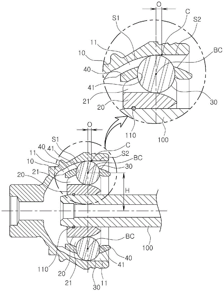
[0026] The constant speed universal joint according to the embodiment of the present invention includes an outer joint part 10 and an inner handpiece part 20. The constant-speed universal joint may realize the function of transmitting the energy of the transmission device to the driving wheel, and the outer joint part 10 may be connected to the driving wheel, and the inner joint part 20 may be connected to the transmission device through the connecting shaft 100. At this time, the inner joint member 20 is connected to the connecting shaft 100 so as to rotate with it, and the fixing ring 110 may be interposed between the inner joint member 20 and the connecting shaft 100 for fixing in the axial direction.

[0027] The constant velocity universal joint according to the embodiment of the present invention may be a constant velocity universal joint having a l...


PUM


Abstract

A constant-velocity universal joint comprises: an outer joint member provided with a plurality of outer ball grooves; an inner joint member provided with a plurality of inner ball grooves, which respectively correspond to the plurality of outer ball grooves; a plurality of torque delivery balls, each of which is guided by the one pair of outer ball grooves and the inner ball grooves; and a ball cage for accommodating the plurality of torque delivery balls. The outer and the inner ball grooves have a dual shape formed by connecting mutually different shapes, and the ratio (O / H) of an offset value (O), which is the distance between lines connecting the center of the plurality of the torque delivery balls while the outer joint member and the inner joint member form an angle of zero (0) degrees with the center point of a curve of the outer ball grooves, with respect to the distance (H) between the center line of the inner joint member and the center of the torque delivery balls while the outer joint member and the inner joint member form an angle of zero (0) degrees, is 0.07 to 0.11.

Description

Technical field [0001] The invention relates to a constant speed universal joint for vehicles. Background technique [0002] The constant-speed universal joint includes an outer joint part with an outer spherical groove, an inner joint part with an inner spherical groove, a moment transmission sphere configured to be respectively guided by an outer sphere groove and an inner sphere groove, and a moment transmission sphere including a moment transmission sphere. Sphere holder. The constant speed universal joint can be interposed between the transmission device and the driving wheel to realize the function of transmitting torque. [0003] The spherical groove of the constant velocity universal joint can be formed by joining parts having different shapes so as to have a double shape and have a larger joint angle (for example, greater than 50 degrees). [0004] In traditional constant velocity universal joints with larger joint angles, the ratio O / H of the offset value O to the distanc...

Claims


Application Information

Patent Timeline
Patent Type & Authority Applications(China)
IPC IPC(8): F16D3/20F16D3/22
CPCF16D3/223F16D3/2237F16D2003/22309Y10S464/906F16D3/20F16D3/22F16D2003/22303
Inventor 李铉一李章瑄金东震郑宰升
Owner ERAE AMS CO LTD
Features
  • R&D
  • Intellectual Property
  • Life Sciences
  • Materials
  • Tech Scout
  • Unparalleled Data Quality
  • Higher Quality Content
  • 60% Fewer Hallucinations
Learn More