Tool holder for cutting insert

A technology for cutting blades and tool holders, which is applied to cutting blades, tools for lathes, accessories for tool holders, etc., and can solve problems such as high bending strength, uneven clamping characteristics of clamping segments, and complicated tool holder manufacturing.

Active Publication Date: 2016-05-25
KENNAMETAL INC
View PDF8 Cites 4 Cited by
  • Summary
  • Abstract
  • Description
  • Claims
  • Application Information

AI Technical Summary

Problems solved by technology

[0006] However, considering this known tool holder, it is disadvantageous that the curved section has a variable bending strength along its width, the bending strength being higher in the raised area
This leads to inhomogeneous clamping properties of the clamped segments
Furthermore, due to the geometry of the dorsal side of the clamping segment, the manufacture of the tool holder is rather complicated

Method used


Image

  • Tool holder for cutting insert
  • Tool holder for cutting insert
  • Tool holder for cutting insert

Examples


Embodiment Construction

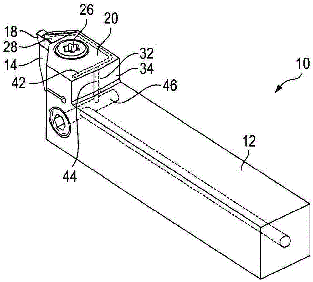
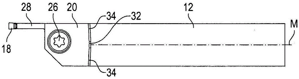
[0021] Figure 1 to Figure 5 A tool holder 10 having a handle 12 is shown. The tool holder 10 can be clamped into a machine tool (such as a lathe) by the handle 12.

[0022] At one end of the shank, referred to herein as the "front end", the shank is provided with a support section 14 on which a mounting seat 16 for the cutting insert 18 is provided. The cutting insert 18 is of the type that can be used especially for turning grooves and notches.

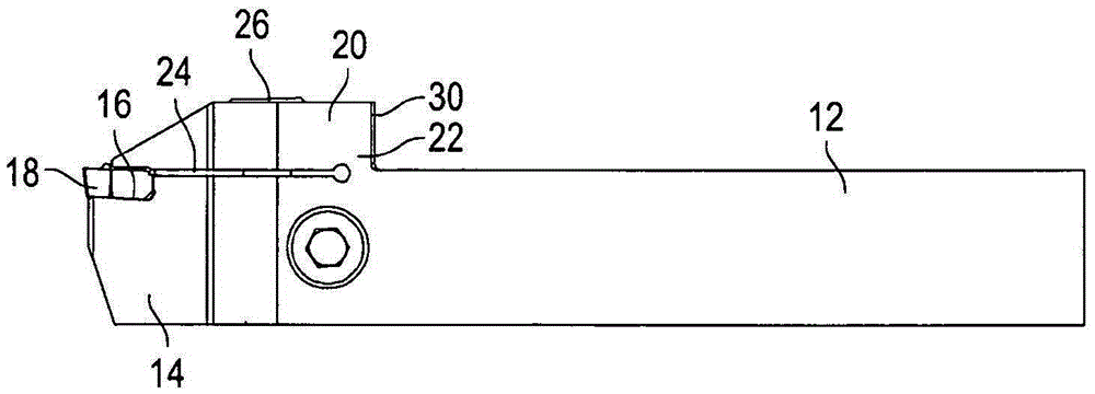
[0023] It is set here above the plane defined by the top side of the handle 12 (see image 3 The clamping section 20 of) is configured to clamp the cutting insert 18 into the mounting seat 16. The clamping section 20 is integrally joined to the handle 12 via the bending section 22. On the side of the curved section 22 facing the shank 12 (ie “upstream” thereof), the support section 14 and the clamping section 20 are separated by a gap 24.

[0024] A clamping element 26 is provided on the clamping section 20, and the clamping section 20 ...


PUM


Abstract

The invention relates to a tool holder (10) for a cutting insert (18), having a shank (12), a counter bearing (14) on which a pocket (16) for a cutting insert (18) is provided, disposed on the front end of the shank, and a clamping segment (20) integrally joined to the shank (12) via a bending segment (22); wherein the clamping segment (20) has a clamping finger (28) and a clamping element (26) such that the clamping finger (28) is capable of acting against the counter bearing segment (14) by means of the clamping element (26), thereby enabling a cutting insert (18) to be clamped between the clamping finger (28) and the counter bearing segment (14); wherein the clamping segment (20) protrudes beyond the top side of the shank (12); and wherein a coolant supply passage (40, 42, 44, 46) extends through the shank (12) and the bending segment (22) into the clamping segment (20); wherein the coolant supply passage (40, 42, 44, 46) has a shank passage (46), a clamping finger passage (40), and a connecting passage (44) that starts from the shank passage (46) and extends through the bending segment (22); characterized in that the connecting passage (44) is disposed in a longitudinal center region of the tool holder (10) and, on its rear side (30) facing toward the shank (12), the clamping segment (20) extends less far in a direction toward the rear end of the shank (12) on both sides of the longitudinal center segment than it does in the longitudinal center segment.

Description

Technical field [0001] The present invention relates to a tool holder for cutting inserts, including: a shank; a support section provided on the front end of the shank, and a mounting seat for the cutting insert is provided on the support section; The connection between the segment and the handle is integrated into an integrated clamping segment, the clamping segment has a clamping finger and a clamping element, so that the clamping finger can be loaded with respect to the support section by means of the clamping element, thereby making The cutting insert can be clamped between the clamping finger and the support section; wherein the clamping section protrudes from the top side of the shank; and wherein the coolant supply channel extends through the shank and the curved section and enters into the clamping In the segment; wherein the coolant supply channel has a handle channel, a clamping finger channel, and a connecting channel starting from the handle channel and extending thr...

Claims


Application Information

Patent Timeline
IPC IPC(8): B23B29/04
CPCB23B27/10B23B29/043B23B2205/02B23B2250/12Y10T407/25B23B29/046
Inventor I·考夫曼A·M·阿布杜尔
Owner KENNAMETAL INC
Why Eureka
Try Eureka