Looper
The technology of a pocketing machine and a needle disc is applied in the field of pocketing machines, which can solve the problems of low work efficiency, insufficient opening width, and high rate of defective fabric stitching, and achieves the effect of improving cloth feeding efficiency and increasing frictional force.
- Summary
- Abstract
- Description
- Claims
- Application Information
AI Technical Summary
Problems solved by technology
Method used
Image

Examples
Embodiment Construction
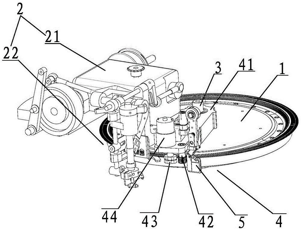
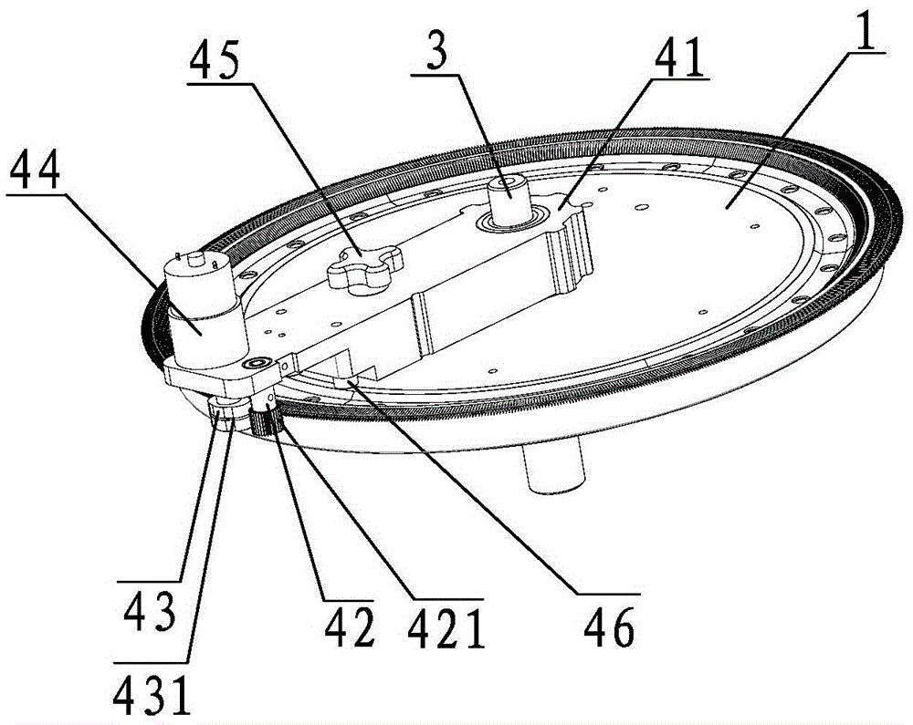
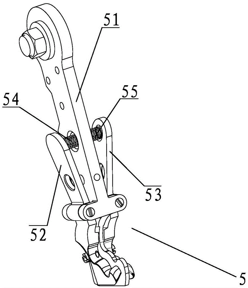
[0012] Such as figure 1 , 2 , 3, what the present invention discloses is a kind of threading machine, comprises the machine head 2 that is fixed on the dial 1 and cooperates with the dial 1, and a guide cloth is movably installed on the dial 1 through a rotating shaft 3 Device 4, the fabric guide device 4 includes a swing arm seat 41, one end of the swing arm seat 41 is movably installed in the middle of the dial 1 through the first rotating shaft 3, and a cloth pressing wheel 42 is movably installed on the lower edge of the other end of the swing arm seat 41 And push cloth wheel 43 and be connected with dial 1, described cloth push wheel 43 is driven by the motor 44 that is installed on the other end upper edge of arm base 41; The bull's-eye bearing 46 is rollingly connected with the dial 1, and a fixed handle 45 is installed on the upper edge of the arm base 41, which can fix the arm base 41 on the dial 1; mechanism 5, the unwinding mechanism 5 is located at the peripheral...
PUM
 Abstract
Description
Claims
Application Information