Compressor valve plate and compressor valve assembly

A compressor and valve plate technology, which is applied in the field of compressors, can solve the problems of uneven force on the suction valve plate of the compressor, reduce the sealing reliability of the valve group, and reduce the reliability of the compressor, so as to achieve uniform force and improve Operational reliability and effect of improving suction efficiency

Active Publication Date: 2018-08-03
GREE ELECTRIC APPLIANCES INC +1
View PDF7 Cites 1 Cited by
  • Summary
  • Abstract
  • Description
  • Claims
  • Application Information

AI Technical Summary

Problems solved by technology

[0004] The contour line shape of the suction hole of the compressor valve plate in the prior art leads to uneven force on the suction valve plate of the compressor, and partial deformation of the suction hole, which reduces the reliability of the valve group seal, which in turn reduces the reliability of the compressor. sex

Method used


Image

  • Compressor valve plate and compressor valve assembly
  • Compressor valve plate and compressor valve assembly
  • Compressor valve plate and compressor valve assembly

Examples


Embodiment Construction

[0027] The present invention will be described in detail below with reference to the accompanying drawings and in conjunction with the embodiments.

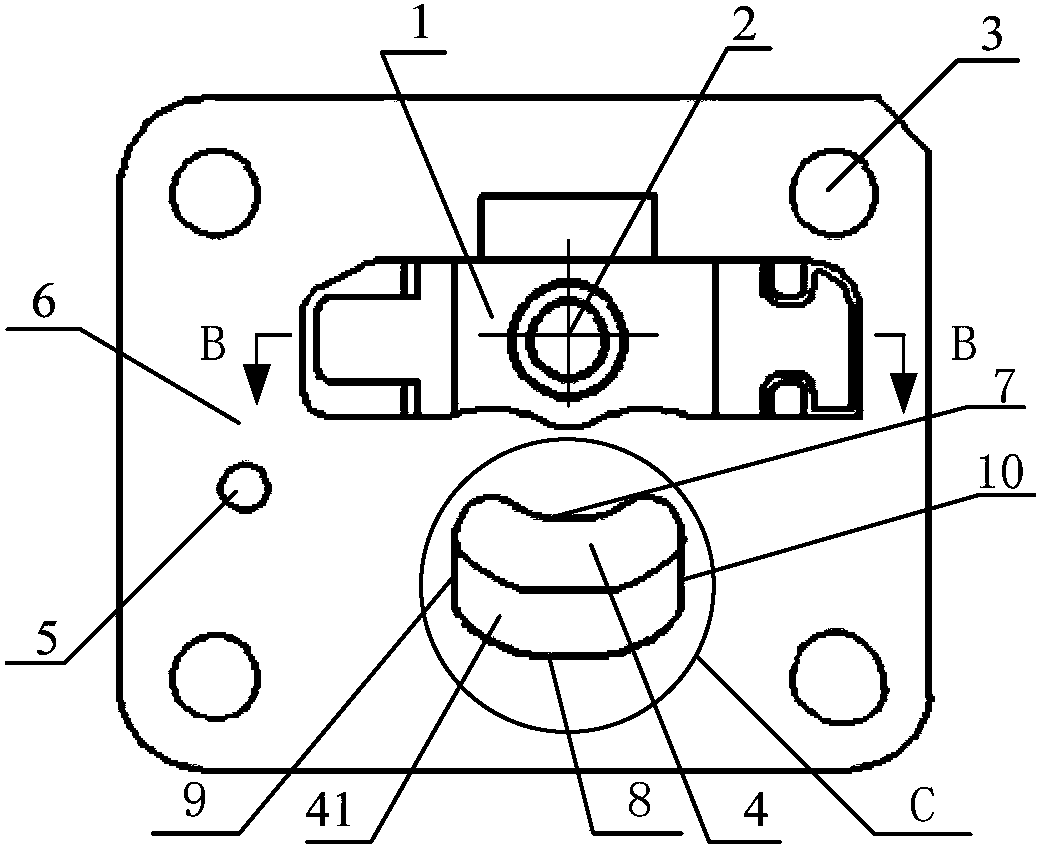
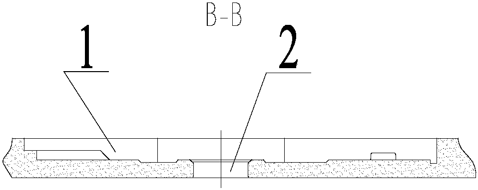
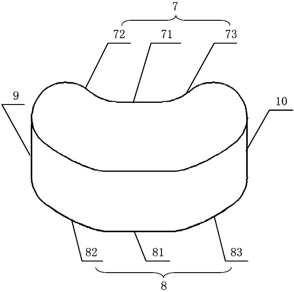
[0028] like Figure 1 to Figure 6 As shown, the present invention provides a compressor valve plate, including a valve plate body 6, a groove 1 is opened on the front of the valve plate body 6, an exhaust hole 2 is opened in the groove 1, and a valve plate body 6 is also opened. There is a suction hole 4, the contour line of the suction hole 4 includes a first curved segment 7 close to the exhaust hole 2 and a second curved segment 8 far away from the exhaust hole 2, the first curved segment 7 and the second curved segment 8 pass through The third circular arc 9 and the fourth circular arc 10 are connected, the first curved segment 7 and the second curved segment 8 both protrude in a direction away from the exhaust hole 2, and the first curved segment 7 includes a first transition straight segment in the middle 71, the second cu...


PUM


Abstract

The invention provides a compressor valve plate and a compressor valve assembly. The compressor valve plate comprises a valve plate body. A groove is formed in the front face of the valve plate body and internally provided with an exhaust hole. An air suction hole is formed in the valve plate body. The contour of the air suction hole comprises a first curve section close to the exhaust hole and a second curve section away from the exhaust hole. The first curve section and the second curve section are connected through a third arc and a fourth arc. The first curve section and the second curve section protrude away from the exhaust hole. The first curve section comprises a first transition straight line section in the middle. The second curve section comprises a second transition straight line section in the middle. By arranging the first transition straight line section on the first curve section of the contour of the air suction hole of the valve plate and arranging the second transition straight line section on the second curve section of the contour line of the air suction hole of the valve plate, an air suction valve block bears force more uniformly, the air suction hole is not prone to the deformation phenomenon, and the running reliability of the air suction valve block is improved.

Description

technical field [0001] The invention relates to the field of compressors, in particular to a compressor valve plate and a compressor valve assembly. Background technique [0002] At present, the valve plates used in refrigerator compressors on the market are basically concave valve plates, and the main structure is similar. The main difference is the outline shape of the suction hole. For example, in Jiaxi Bella, the outline of the suction hole is connected by three circular arc lines and a straight line (closer to the exhaust port side); Dongbei AZ: It is connected by an arc line (away from the exhaust port side) and three straight lines in turn, accompanied by Chamfer; Dongbei L series: circular structure; Embraco (EM2C4OCLT): ring; HYS60MTU: elliptical structure; HYE50MDU: incomplete circular structure; Wanbao ETH: semicircle and arc connected; LG: circular structure, etc. . [0003] The valve plate structure in the patent scheme with the patent number of ZL01812881.5, ...

Claims


Application Information

Patent Timeline
Patent Type & Authority Patents(China)
IPC IPC(8): F04B39/10
CPCF04B39/1066
Inventor 王良泽崔中徐敏陈娟娟卢研浩
Owner GREE ELECTRIC APPLIANCES INC
Why Eureka
Try Eureka