Bayonet connecting structure and bed

A technology for connecting structures and bed boards, which is applied in the direction of connecting components, bed frames, furniture, etc., can solve the problems of low connection firmness, low locking force, and limited connection strength, so as to improve firmness, increase locking force, The effect of increasing the strength of locking

Active Publication Date: 2016-05-25
舒土石
View PDF8 Cites 2 Cited by
  • Summary
  • Abstract
  • Description
  • Claims
  • Application Information

AI Technical Summary

Problems solved by technology

[0005] The purpose of the present invention is to provide a bayonet connection structure and a bed, aiming to solve the problems in the prior art that due to the limited connection strength between the screwed drawer bar and the bed frame, the firmness of the connection and the strength of the locking are relatively low. question

Method used


Image

  • Bayonet connecting structure and bed
  • Bayonet connecting structure and bed
  • Bayonet connecting structure and bed

Examples


Embodiment Construction

[0020] In order to make the object, technical solution and advantages of the present invention clearer, the present invention will be further described in detail below in conjunction with the accompanying drawings and embodiments. It should be understood that the specific embodiments described here are only used to explain the present invention, not to limit the present invention.

[0021] The implementation of the present invention will be described in detail below in conjunction with specific embodiments.

[0022] With reference to figure, it is the preferred embodiment that the present invention provides.

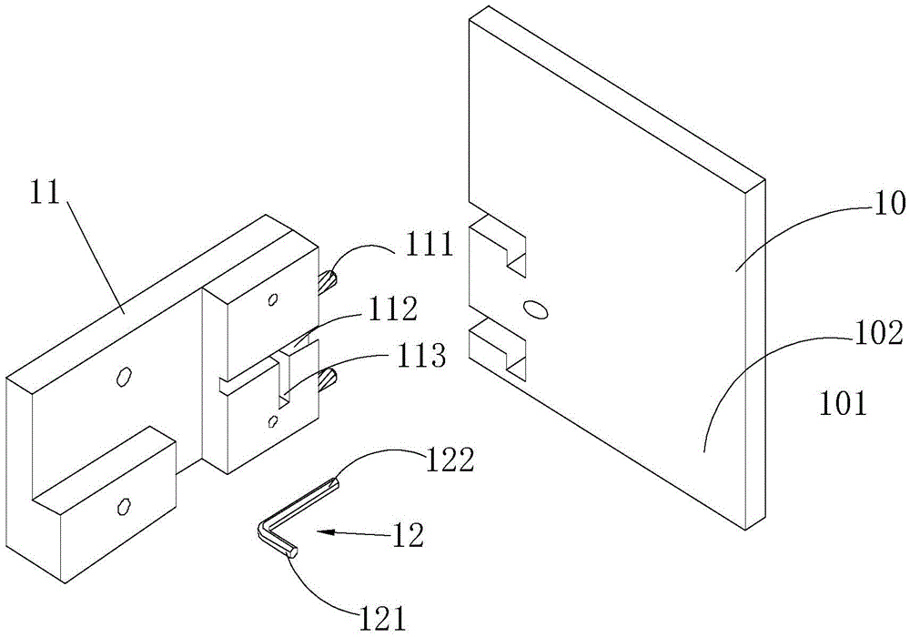
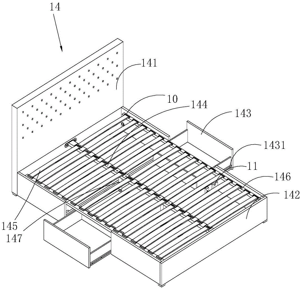
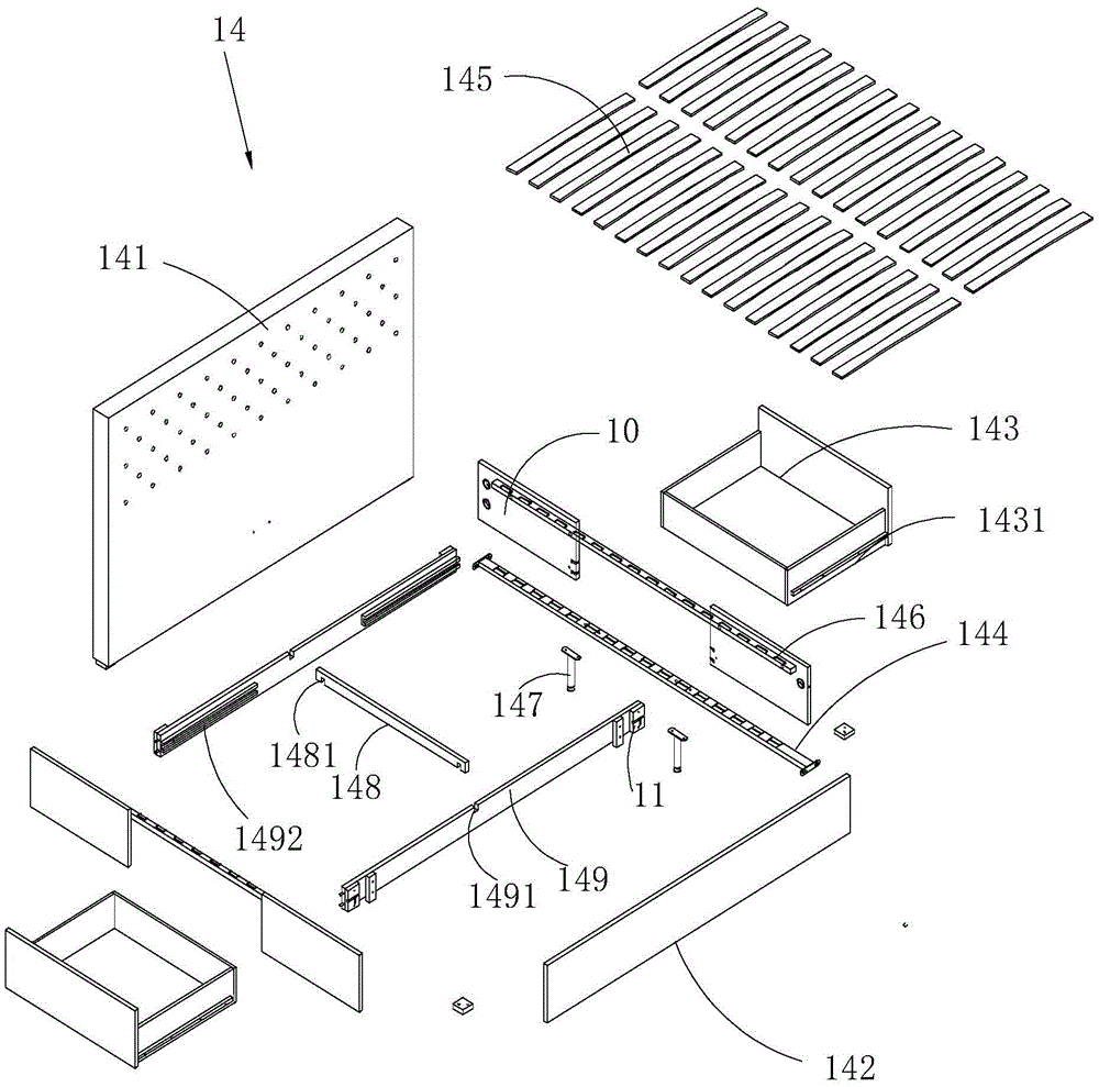
[0023] The bayonet connection structure provided in this embodiment can be used in the connection process between the drawer bar 149 and the bed frame to realize the turning connection between the drawer bar 149 and the two ends of the bed frame; or it can be used in other In the connection of two objects connected at an angle.

[0024] A bayonet connection structure, ...


PUM


Abstract

The invention relates to a bayonet connecting structure and a bed. The bayonet connecting structure comprises multiple L-type grooves formed in a second plate and multiple convex pins arranged at the inner side of a first plate, the straight edge of the inner end of each L-type groove extends downwards, and each convex pin is embedded into the corresponding L-type groove; the bayonet connecting structure comprises a positioning pin groove formed in the first plate, a positioning hole formed in the second plate and a positioning pin, an embedding part embedded into the positioning pin groove is formed at the inner end of the positioning pin, the outer end of the positioning pin extends outwards to form a positioning part inserted into the positioning hole, and the positioning hole is located among the multiple L-type grooves. The positioning pin groove and the positioning hole are connected, the ends of the two plates are connected in a turning mode, and the positioning pin rotates downwards to generate acting force pressing downwards to form locking force; the convex pins on the first plate are embedded into the L-type grooves in the second plate, the first plate will drive the convex pins to be completely embedded into the inner ends of the L-type grooves under the action of gravity, connection is firmer, and locking force is larger.

Description

technical field [0001] The present invention relates to a coupling structure, especially a bayonet coupling structure and a bed using this structure. Background technique [0002] Drawers are generally embedded in most of the existing bed frames, which are mainly used to place some small parts as storage space. [0003] A bed with drawers generally locks two drawer horizontal bars by screws in its bed frame, and a chute is provided in the fixing bar, and the drawer is slidably connected to the chute, so that the bed frame and the drawer are combined into one. [0004] However, in the above-mentioned connection method, due to the limited connection strength of the screws, the firmness of the connection and the locking force are low, and when the bed and the drawer are disassembled, it is difficult to disassemble. The bed frame was held at a vertical angle, making it difficult for the drawers to pull out smoothly. Contents of the invention [0005] The purpose of the prese...

Claims


Application Information

Patent Timeline
Patent Type & Authority Applications(China)
IPC IPC(8): F16B12/56F16B12/60A47C19/22A47C19/02
CPCA47C19/005A47C19/021A47C19/028A47C19/22F16B12/56F16B12/60
Inventor 舒土石
Owner 舒土石
Why Eureka
Try Eureka