Sample testbed for EBSD (Electron Back-Scattered Diffraction) testing

A technology of sample testing and guide rails, which is applied in the direction of measuring devices, material analysis using wave/particle radiation, instruments, etc., can solve the problems of backscattering area offset, inaccurate test results, easy to change image position, etc., to ensure The effect of stability

Active Publication Date: 2016-05-25
HARBIN INST OF TECH
View PDF9 Cites 5 Cited by
  • Summary
  • Abstract
  • Description
  • Claims
  • Application Information

AI Technical Summary

Problems solved by technology

[0004] In order to solve the problem that the sample stuck on the sample test bench with conductive adhesive will move during the test, the position of the image will easily change, and the backscattering area will shift, resulting in inaccurate test results, and further provides a method for EBSD Sample Test Bench for Testing

Method used


Image

  • Sample testbed for EBSD (Electron Back-Scattered Diffraction) testing
  • Sample testbed for EBSD (Electron Back-Scattered Diffraction) testing
  • Sample testbed for EBSD (Electron Back-Scattered Diffraction) testing

Examples


specific Embodiment approach 1

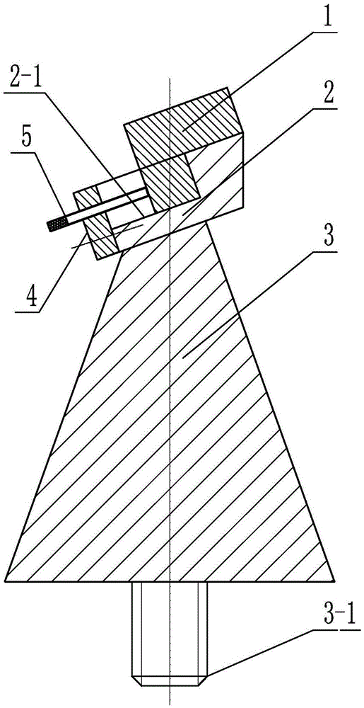
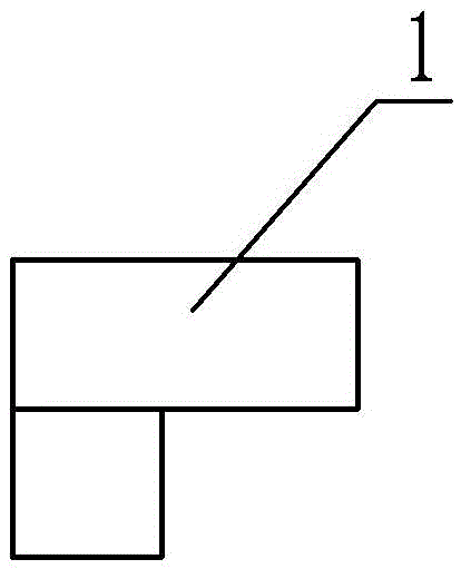
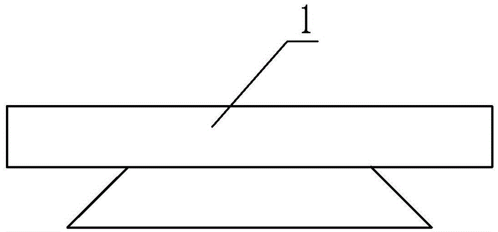
[0017] Specific implementation mode one: as Figure 1-7 As shown, the sample test bench for EBSD testing in this embodiment includes a slider 1, a guide rail 2, a base 3, a limit plate 4 and a jacking screw 5, the guide rail 2 is obliquely fixed on the upper end surface of the base 3, and the guide rail 2 Dovetail groove 2-1 is processed on the upper end surface of the guide rail 2, the angle between the length direction of the dovetail groove 2-1 of the guide rail 2 and the vertical direction is 70°, the upper part of the slider 1 is in the shape of a cuboid, and the lower part of the slider 1 It is a dovetail shape, the lower part of the slider 1 is located in the dovetail groove 2-1 of the guide rail 2 and the two are slidably connected, the angle between the upper end surface of the slider 1 and the vertical direction is 70°, and the lower part of the limit plate 4 It is detachably connected with the lower part of the guide rail 2 , and the middle part of the limiting plat...

specific Embodiment approach 2

[0019] Specific implementation mode two: as figure 1 , 5 As shown in and 6, the middle part of the lower end surface of the base 3 in this embodiment is provided with a stud 3-1. It is convenient to fix the sample test bench. Other components and connections are the same as those in the first embodiment.

specific Embodiment approach 3

[0020] Specific implementation mode three: as figure 1 As shown, in this embodiment, the lower part of the limiting plate 4 and the lower part of the guide rail 2 are detachably connected by two connecting bolts. With such a design, it is easy to disassemble and install. Other compositions and connections are the same as those in Embodiment 1 or 2.


PUM


Abstract

The invention discloses a sample testbed for EBSD (Electron Back-Scattered Diffraction) testing, relating to a sample testbed and solving the problems that, when being adhered to a sample testbed with a conductive adhesive, a sample will move in a testing process, the position of an image is likely to change, a back scattering region deviates, and the testing result is inaccurate. A guide rail is obliquely and fixedly arranged on the upper end surface of a base; a dovetail groove is machined in the upper end surface of the guide rail; an included angle between the length direction and the vertical direction of the dovetail groove of the guide rail is 70 degrees; the upper part of a sliding block is of a cuboid shape, and the lower part of the sliding block is of a dovetail shape; the lower part of the sliding block is positioned in the dovetail groove of the guide rail and is in sliding connection with the dovetail groove; an included angle between the upper end surface and the vertical direction of the sliding block is 70 degrees; the lower part of a limiting plate is detachably connected with the lower part of the guide rail; a jackscrew is arranged in the middle of the limiting plate, and one end of the jackscrew is in contact with the sliding block. The sample testbed disclosed by the invention is used for EBSD testing.

Description

technical field [0001] The invention relates to a sample test bench, in particular to a sample test bench for EBSD testing. Background technique [0002] In a scanning electron microscope (SEM), an electron beam incident on a sample interacts with the sample to produce several different effects, one of which is diffraction on regularly arranged lattice planes within each crystal or grain. Diffraction from all atomic planes constitutes a "diffraction pattern", which can be viewed as a map of the angular relationship between atomic planes in a crystal. Since the 1990s, the analysis technology of electron backscattering patterns (EBSP for short) crystal micro-region orientation and crystal structure assembled on SEM has made great progress, and has been applied in the microstructure of materials and microweave. Widely used in structural representation. This technique is also called Electron Backscattered Diffraction (EBSD for short) or Orientation Imaging Microscopy (OIM for ...

Claims


Application Information

Patent Timeline
Patent Type & Authority Applications(China)
IPC IPC(8): G01N23/203
CPCG01N23/203
Inventor 范国华唐光泽曹国剑
Owner HARBIN INST OF TECH
Why Eureka
Try Eureka