
Mechanism for continuous drilling of workpieces

A technology for workpieces and connecting rods, which is applied in the field of mechanisms for continuous drilling of workpieces. It can solve problems such as drill bit offset, uneven force on the drill bit, unqualified inclined holes, etc., and achieve the effect of ensuring reliability and avoiding motion interference.

Active Publication Date: 2018-03-13
创客帮(山东)科技服务有限公司
View PDF6 Cites 0 Cited by
  • Summary
  • Abstract
  • Description
  • Claims
  • Application Information

AI Technical Summary

Problems solved by technology

In the prior art, it is relatively easy to process a hole perpendicular to the surface of the workpiece. It is only necessary to face the drill bit to the surface of the workpiece and keep the drill bit perpendicular to the surface of the workpiece; The hole is relatively difficult, and it is difficult to ensure the machining accuracy. This is because in the process of processing inclined holes, it is necessary to maintain a certain inclination between the drill bit and the surface of the workpiece, and in the process of drilling, because the force received by the drill bit is not perpendicular to the drill bit Therefore, it is easy to cause uneven force on the drill bit, which will cause the drill bit to deviate when drilling inclined holes, which will cause the processed inclined holes to be unqualified; in addition, sometimes multiple holes are processed on the same workpiece, and multiple The angle between two holes, at this time, the structure of the swing drill angle and the stability requirements during the drilling process of the drill bit become higher again.
To sum up, in the prior art, the precision of the device for continuously punching the workpiece is not high enough, and the angle between the straight hole and the inclined hole cannot be guaranteed when processing the straight hole and the inclined hole at the same time.

Method used


Image

  • Mechanism for continuous drilling of workpieces
  • Mechanism for continuous drilling of workpieces
  • Mechanism for continuous drilling of workpieces

Examples


Embodiment Construction

[0015] The present invention will be further described below in conjunction with the accompanying drawings and specific embodiments.

[0016] Working principle of the present invention:

[0017] First, the workpiece is placed on the base, and the workpiece is clamped and positioned by the fixture;

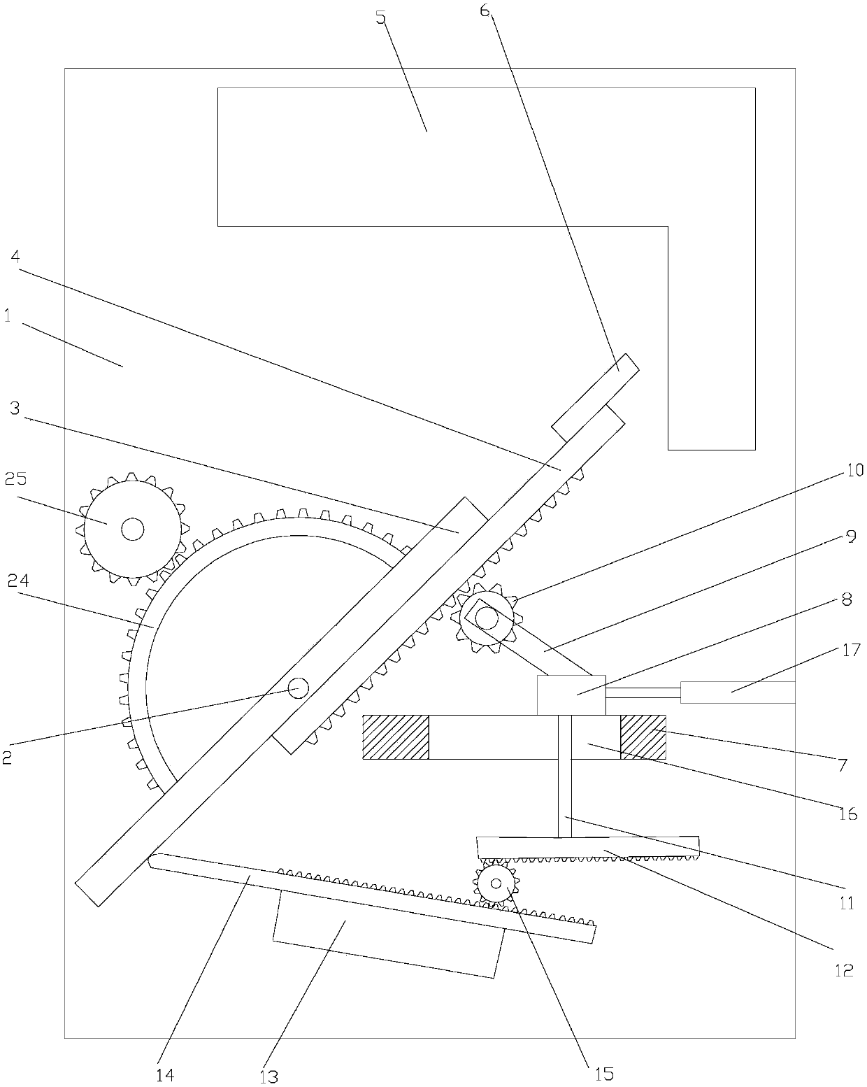
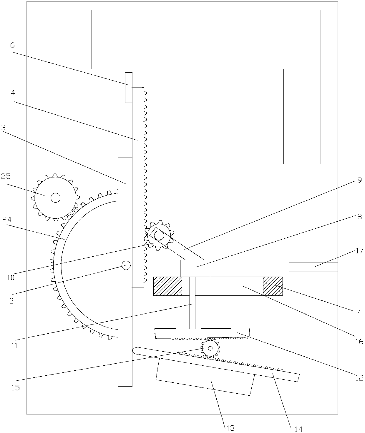
[0018] Then, the first cylinder works to drive the slider to move horizontally on the platform, such as figure 1 As shown, the first cylinder drives the slider to move to the left, and the slider pushes the first linear rack through the first gear at the upper end of the connecting rod, and then pushes the guide rod to rotate counterclockwise around the rotating shaft. When the slider moves to the left, The second linear rack also moves to the left, and the second linear rack drives the third linear rack to move to the right through the meshing transmission of the second gear, and the left end of the third linear rack is always against the lower end of the guide rod, That is to s...


PUM


Abstract

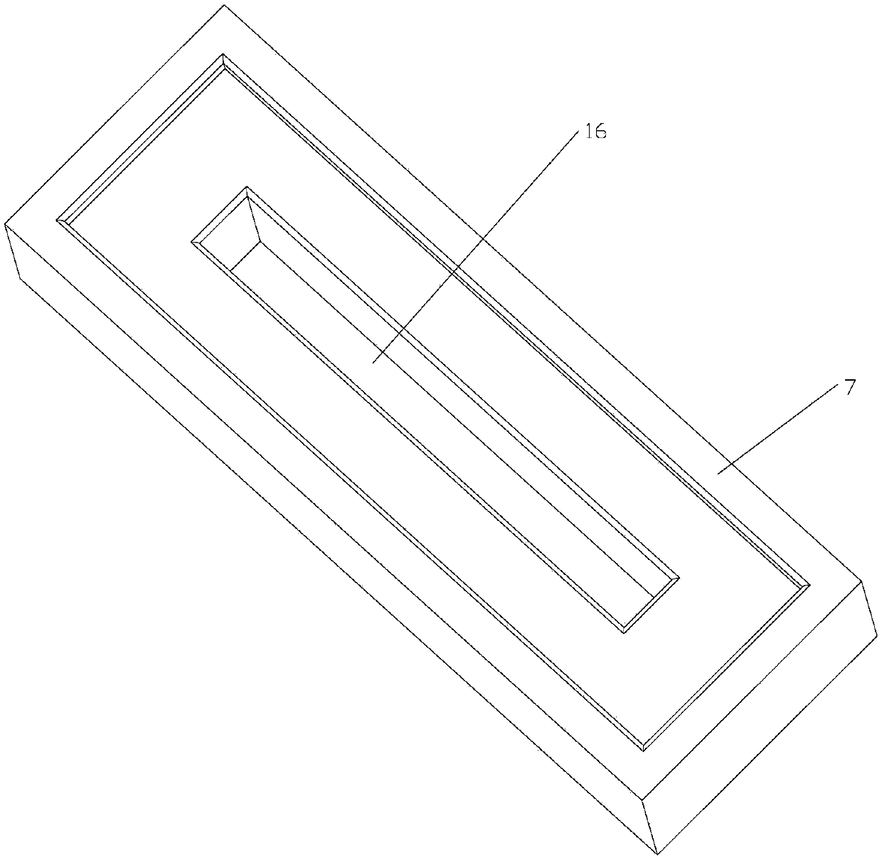
The invention discloses a mechanism for continuously punching workpieces. The mechanism comprises a base (1) which is rotatably connected with a guide rod (3) through a rotating shaft (2), the guide rod (3) is slidably connected with a first linear rack (4) through a dovetail groove, and a drilling machine (6) used for punching a workpiece (5) placed on the base (1) is arranged on the first linear rack (4); a platform (7) is arranged on the base (1) and slidably connected with a slider (8) through the dovetail groove, and a connecting rod (9) is obliquely arranged on the slider (8). The mechanism is higher in punching accuracy and capable of guaranteeing included angles among multiple holes when the holes are processed at the same time.

Description

technical field [0001] The invention relates to the technical field of drilling, in particular to a mechanism for continuously drilling workpieces. Background technique [0002] Currently, drilling holes in workpieces is a routine machining operation. In the prior art, it is relatively easy to process a hole perpendicular to the surface of the workpiece. It is only necessary to face the drill bit to the surface of the workpiece and keep the drill bit perpendicular to the surface of the workpiece; The hole is relatively difficult, and it is difficult to ensure the machining accuracy. This is because in the process of processing inclined holes, it is necessary to maintain a certain inclination between the drill bit and the surface of the workpiece, and in the process of drilling, because the force received by the drill bit is not perpendicular to the drill bit Therefore, it is easy to cause uneven force on the drill bit, which will cause the drill bit to deviate when drilling...

Claims


Application Information

Patent Timeline
Patent Type & Authority Patents(China)
IPC IPC(8): B23B41/00B23B47/00B23B47/18
CPCB23B41/00B23B47/00B23Q5/34
Inventor 王奇峰许海波
Owner 创客帮(山东)科技服务有限公司
Learn More