
Differential-speed dynamic coupling device

A power coupling and differential technology, applied in the direction of differential transmission, transmission, transmission parts, etc., can solve problems such as affecting the normal power transmission of the vehicle, reducing the life of the differential, and difficult to assemble needle rollers, and achieve a simplified new Design and trial production, prevent breakage, and run well

Inactive Publication Date: 2010-11-24
JILIN UNIV
View PDF4 Cites 8 Cited by
  • Summary
  • Abstract
  • Description
  • Claims
  • Application Information

AI Technical Summary

Problems solved by technology

In this case, a pure needle roller bearing solution was proposed, that is, needle rollers were evenly installed between the planetary gear and the planetary gear shaft, in order to convert the sliding friction between them into rolling friction, so as to reduce its sliding wear. However, this solution has problems such as difficult assembly of the needle rollers, motion interference between the needle rollers, breakage of the planetary gear shaft, partial bending of the roller needles, and partial breakage of the needle rollers, which not only greatly reduces the life of the differential, but also seriously affects the vehicle. normal power transmission

Method used


Image

  • Differential-speed dynamic coupling device
  • Differential-speed dynamic coupling device
  • Differential-speed dynamic coupling device

Examples


Embodiment Construction

[0020] The present invention is described in detail below in conjunction with accompanying drawing:

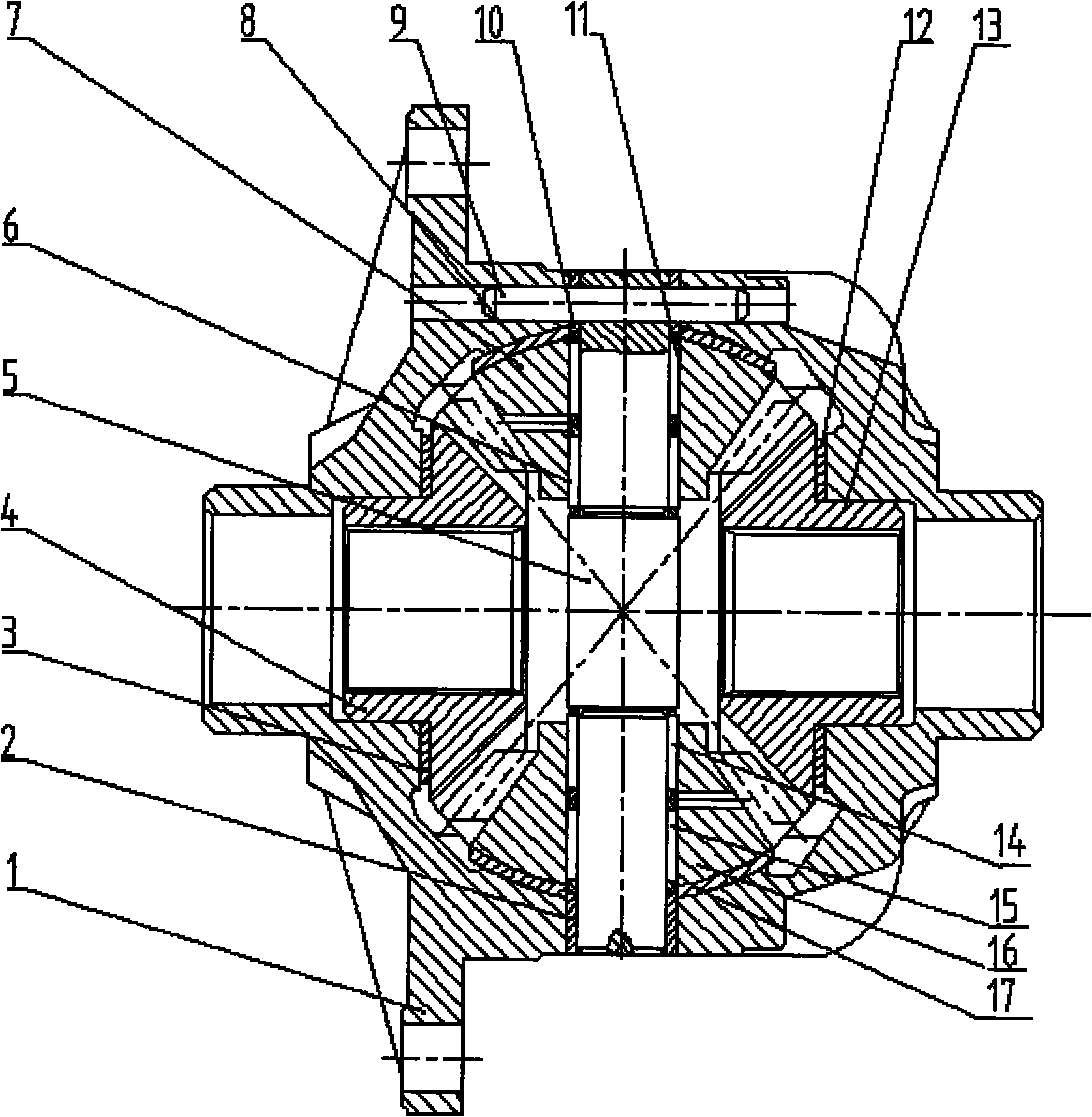
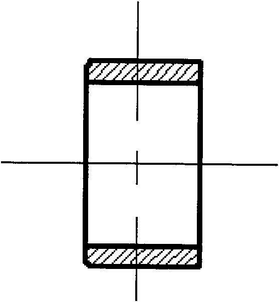
[0021] refer to figure 1 , in order to solve the problem that the "pure needle roller bearing" scheme adopted in the prior art has difficulty in assembling the needle rollers, prone to movement interference between the needle rollers, breaking the planetary gear shaft, and partially bending or breaking the needle rollers, the present invention proposes Differentials using needle roller bearings with cages for use as power coupling devices for series-type hybrid electric vehicles. In other words, the traditional differential can be applied to hybrid electric vehicles as a power coupling device only by partially modifying the internal structure of the traditional differential.

[0022] The differential power coupling device of the present invention includes a differential case 1, a circular sleeve without holes 2, a left side gear spacer 3, a left side gear (bevel gear) 4, a pl...


PUM


Abstract

The invention discloses a differential-speed dynamic coupling device, aiming at solving the problem of sliding friction between a planetary gear and a planetary gear shaft in a traditional differential mechanism. The differential-speed dynamic coupling device comprises a differential mechanism casing, a left half shaft gear, an upper planetary gear, a right half shaft gear, a lower planetary gear, a circular sleeve without a hole, a planetary gear shaft, an upper needle bearing No. 1, an upper needle bearing No. 2, a circular sleeve with a hole, a lower needle bearing No. 1, a lower needle bearing No. 2 and the like, wherein the upper needle bearing No. 1, the upper needle bearing No. 2, the circular sleeve with a hole, and the lower needle bearing No. 1, the lower needle bearing No. 2 and the circular sleeve without a hole are sleeved on the upper end and the lower end of the planetary gear shaft in sequence, the planetary gear shaft which is sleeved with the circular sleeve with a hole and the circular sleeve without a hole is installed in an upper end hole and a lower end hole of the differential mechanism casing, and the circular sleeve without a hole and the lower inner hole of the differential casing form the interference fit. The upper planetary gear and the lower planetary gear which are installed on the upper end and the lower end of the planetary gear shaft are respectively and simultaneously meshed with the left half shaft gear and the right half shaft gear which are arranged in the left end hole and the right end hole of the differential mechanism casing.

Description

technical field [0001] The present invention relates to a power coupling device, more specifically, the present invention relates to a differential power coupling device applied to a hybrid electric vehicle. Background technique [0002] HEV-Hybrid Electric Vehicle (HEV-Hybrid Electric Vehicle, generally refers to gasoline-electric hybrid vehicle) realizes the efficient coupling of the power system of the whole vehicle through the combination of the engine, the electric motor and the generator, so that the fuel economy of the whole vehicle is significantly improved. How to realize the power distribution between the engine, motor and generator of hybrid electric vehicles is one of the key problems that must be solved in the development of hybrid electric vehicles. The power coupling form and structure determine the difficulty and direction of HEV power system research and development, which is related to the progress and level of product development, and is a key step in HEV ...

Claims


Application Information

Patent Timeline
Patent Type & Authority Applications(China)
IPC IPC(8): F16H48/06F16H57/08F16C3/02
CPCF16H48/08
Inventor 曾小华王庆年宋大凤郑帅于永涛赵祥磊聂利卫苏天晨王伟王加雪
Owner JILIN UNIV
Learn More