Overvoltage, undervoltage and power-off protection circuit formed by MOS transistor

A technology of over-voltage, under-voltage and power-off protection, which is applied in the direction of emergency protection circuit device, protection for over-voltage response, emergency protection device for automatic disconnection, etc. It can solve the influence of power supply reliability, power restart, integration Problems such as high circuit prices, to achieve the effect of miniaturization integration, cost saving, and circuit simplification

Inactive Publication Date: 2016-05-25
SUZHOU R&D CENT OF NO 214 RES INST OF CHINA NORTH IND GRP
View PDF9 Cites 12 Cited by
  • Summary
  • Abstract
  • Description
  • Claims
  • Application Information

AI Technical Summary

Problems solved by technology

Oscillating output pulses will continuously cause the power supply to restart, which will have an impact on the reliability of the power supply itself, and cannot check the load fault online
There are also circuits composed of two TL431 and PMOS switch tubes, but the price of TL431 integrated circuits is higher
Chinese invention patent application 201310656913.4, an overvoltage shutdown protection circuit, the disadvantage is that it cannot perform undervoltage shutdown protection
Chinese invention patent application 201310718375.7, used in the undervoltage and overvoltage protection circuit of the power circuit, the disadvantage is that the shutdown protection is performed by detecting the current exceeding the limit value, instead of directly performing the shutdown protection on the voltage exceeding the limit value

Method used


Image

  • Overvoltage, undervoltage and power-off protection circuit formed by MOS transistor
  • Overvoltage, undervoltage and power-off protection circuit formed by MOS transistor

Examples


Embodiment Construction

[0020] The present invention will be further described below in conjunction with the accompanying drawings. The following examples are only used to illustrate the technical solution of the present invention more clearly, but not to limit the protection scope of the present invention.

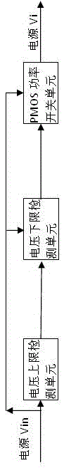
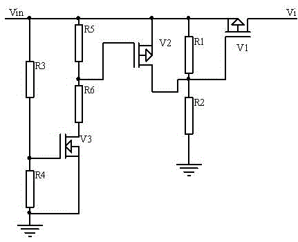
[0021] Such as figure 1 As shown, the present invention includes an upper limit voltage detection unit, a lower limit voltage detection unit and a PMOS power switch unit. The NMOS transistor, the PMOS transistor and four resistors constitute the upper limit voltage detection unit; the other two resistors constitute the lower limit voltage detection unit. The PMOS power switch unit includes a PMOS power switch tube.

[0022] When the voltage exceeds the set upper limit detection voltage, the two resistors in the upper limit voltage detection unit divide the voltage, and when the generated voltage exceeds the threshold voltage of the NMOS transistor, the NMOS transistor is turned on, and the two...


PUM


Abstract

The invention discloses an overvoltage, undervoltage and power-off protection circuit formed by an MOS transistor. The overvoltage, undervoltage and power-off protection circuit comprises an upper limit voltage detection unit, a lower limit voltage detection unit, and a PMOS power switch tube, wherein the upper limit voltage detection unit comprises an NMOS transistor, a PMOS transistor, a third resistor, a fourth resistor, a fifth resistor and a sixth resistor; the lower limit voltage detection unit comprises a first resistor and a second resistor connected in series; the third resistor and the fourth resistor are connected in series between the power supply end and the power supply ground; the shared junction point of the third resistor and the fourth resistor is connected with the grid electrode of the NMOS transistor; the fifth resistor and the sixth resistor are connected in series between the drain electrode of the NMOS transistor and the power supply end; the shared connecting end of the fifth resistor and the sixth resistor is connected to the grid electrode of the PMOS transistor; the source electrode of the PMOS transistor is connected with the power supply end; and the drain electrode of the PMOS transistor is connected with the common connecting end of the first resistor and the second resistor. According to the circuit, power supply restart is not caused in undervoltage or overvoltage switch off; and in addition, the circuit is simple in structure, and capable of realizing miniaturization of the power supply, and saving cost.

Description

technical field [0001] The invention relates to an overvoltage and undervoltage power-off protection device composed of MOS tubes, which belongs to the technical field of circuits. Background technique [0002] The undervoltage and overvoltage protection device of the isolated switching power supply is generally composed of a reference source, a comparator and a MOS switch. Both the comparator and the reference source need two circuits, and they need power supply. The structure is complex and the cost is high. There are also output overvoltage protection devices that turn off the primary side controller, and are divided into two protection forms: permanently shutting off the output when a fault occurs and oscillating output pulses when a fault occurs. Oscillating output pulses will continuously cause the power supply to restart, which will have an impact on the reliability of the power supply itself, and cannot check the load fault online. There are also circuits composed o...

Claims


Application Information

Patent Timeline
Patent Type & Authority Applications(China)
IPC IPC(8): H02H3/20H02H3/24
CPCH02H3/207H02H3/24
Inventor 桑泉杨翠侠
Owner SUZHOU R&D CENT OF NO 214 RES INST OF CHINA NORTH IND GRP
Why Eureka
Try Eureka