Frequency offset estimation method and apparatus for burst-mode signal
A frequency offset estimation and burst signal technology, applied in the field of digital communication, can solve the problems of difficulty in accurately estimating short burst frame frequency offset value, large frequency offset estimation error, etc., to solve the critical inversion of phase angle and improve frequency offset. Estimation accuracy, effect of suppressing influence
- Summary
- Abstract
- Description
- Claims
- Application Information
AI Technical Summary
Problems solved by technology
Method used
Image
Examples
Embodiment 1
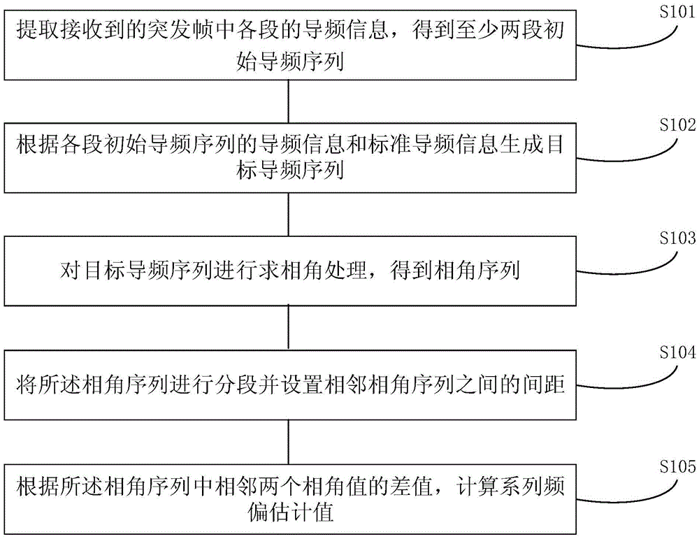
[0050] Such as figure 1 As shown, it is a schematic flow chart of the frequency offset estimation method for burst signals provided in this embodiment, which specifically includes the following steps:
[0051] Step S101, extracting the pilot information of each segment in the received burst frame to obtain at least two initial pilot sequences;
[0052] This embodiment is applicable to frequency offset estimation of a burst frame containing two or more discontinuous pilot sequences. A burst frame usually includes a data segment and a pilot segment, because the data receiver knows the symbol information contained in the pilot segment. Using the received pilot information and the known standard pilot information, the frequency deviation of the received burst frame can be estimated.
[0053] The frequency offset estimation method of this solution makes full use of each segment of pilot information in the burst frame structure, and simultaneously utilizes sequences of multiple se...
Embodiment 2
[0077] This embodiment provides a specific frequency offset estimation method for a burst signal in combination with the structure of the burst frame, as follows:
[0078] The structure of the burst frame containing two pieces of pilot information is as follows figure 2 shown.
[0079] The pilot code of the pilot sequence is divided into two sections, one section is pilot1, and its length is L1; the other section is pilot2, and its length is L2. The data section is also divided into two sections, the first section is Data1, and its data length is D1; the second section is Data2, and its length is D2. So the length of the pilot code in the burst frame structure is L=L1+L2; the data length in the burst frame structure is D=D1+D2; the burst frame length is N=L+D; wherein the pilot sequence pilot1 and The position coordinates of each data of the pilot sequence pilot2 are P1=[1,2,...,L1] and P2=[L1+D1+1,...,L1+D1+L2]; the position P of the pilot sequence=[P1 , P2].
[0080] ...
Embodiment 3
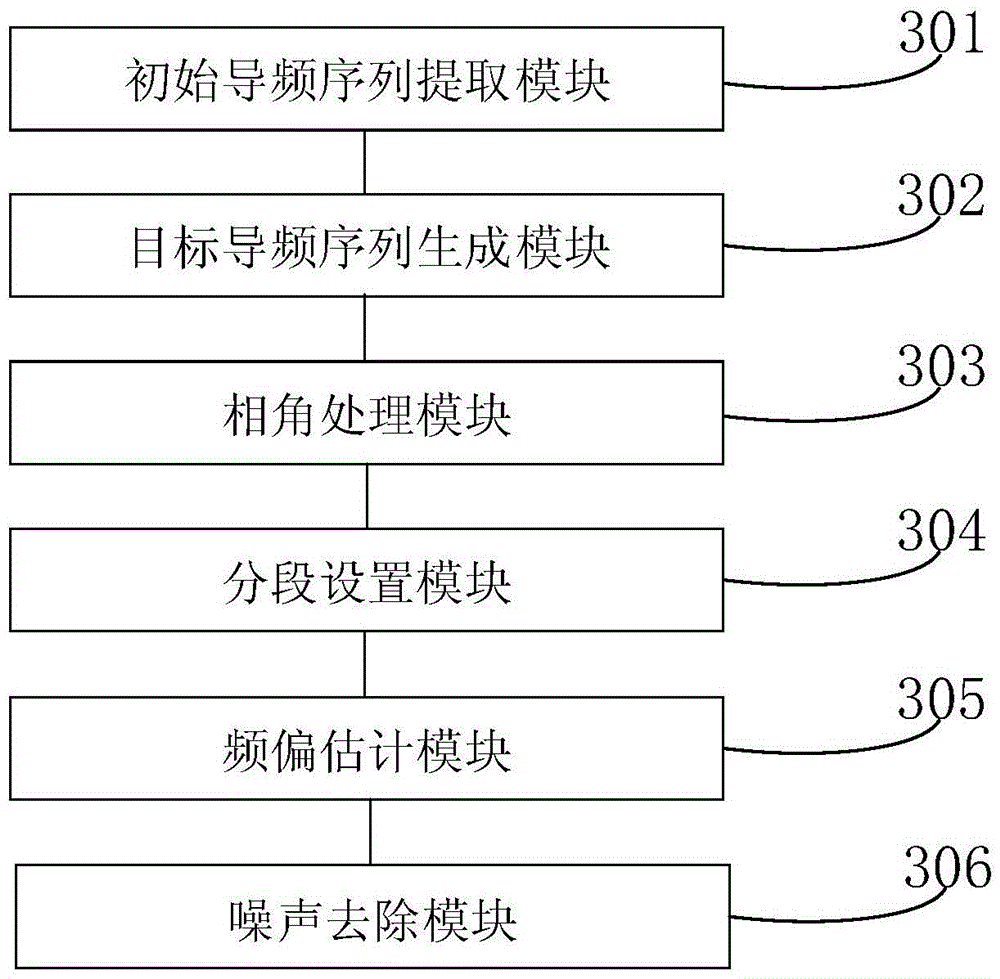
[0095] Corresponding to the above method, this implementation provides a frequency offset estimation device for burst signals, such as image 3 The schematic diagram of the device composition shown includes:
[0096] The initial pilot sequence extraction module 301 is used to extract the pilot information of each segment in the received burst frame to obtain at least two initial pilot sequences;
[0097] A target pilot sequence generation module 302, configured to generate a target pilot sequence according to the pilot information and standard pilot information of each initial pilot sequence;
[0098] A phase angle processing module 303, configured to perform phase angle processing on the target pilot sequence to obtain a phase angle sequence;
[0099] Segment setting module 304, configured to segment the phase angle sequence and set the distance between adjacent phase angle sequences;
[0100] The frequency offset estimation module 305 is configured to calculate a series of...
PUM
 Abstract
Description
Claims
Application Information
 - R&D
- Intellectual Property
- Life Sciences
- Materials
- Tech Scout
- Unparalleled Data Quality
- Higher Quality Content
- 60% Fewer Hallucinations
Browse by: Latest US Patents, China's latest patents, Technical Efficacy Thesaurus, Application Domain, Technology Topic, Popular Technical Reports.
© 2025 PatSnap. All rights reserved.Legal|Privacy policy|Modern Slavery Act Transparency Statement|Sitemap|About US| Contact US: help@patsnap.com


