Needle shields with specific roughness

A technology of roughness and shield, applied in the direction of needles, instruments introduced into the body, hypodermic instruments, etc., can solve the problem of difficulty in removing the needle shield, etc., and achieve the effect of reducing the pull-out force

Active Publication Date: 2019-12-20
BECTON DICKINSON FRANCE
View PDF1 Cites 0 Cited by
  • Summary
  • Abstract
  • Description
  • Claims
  • Application Information

AI Technical Summary

Problems solved by technology

This phenomenon makes it difficult to remove the needle shield when using the syringe

Method used


Image

  • Needle shields with specific roughness

Examples


Embodiment Construction

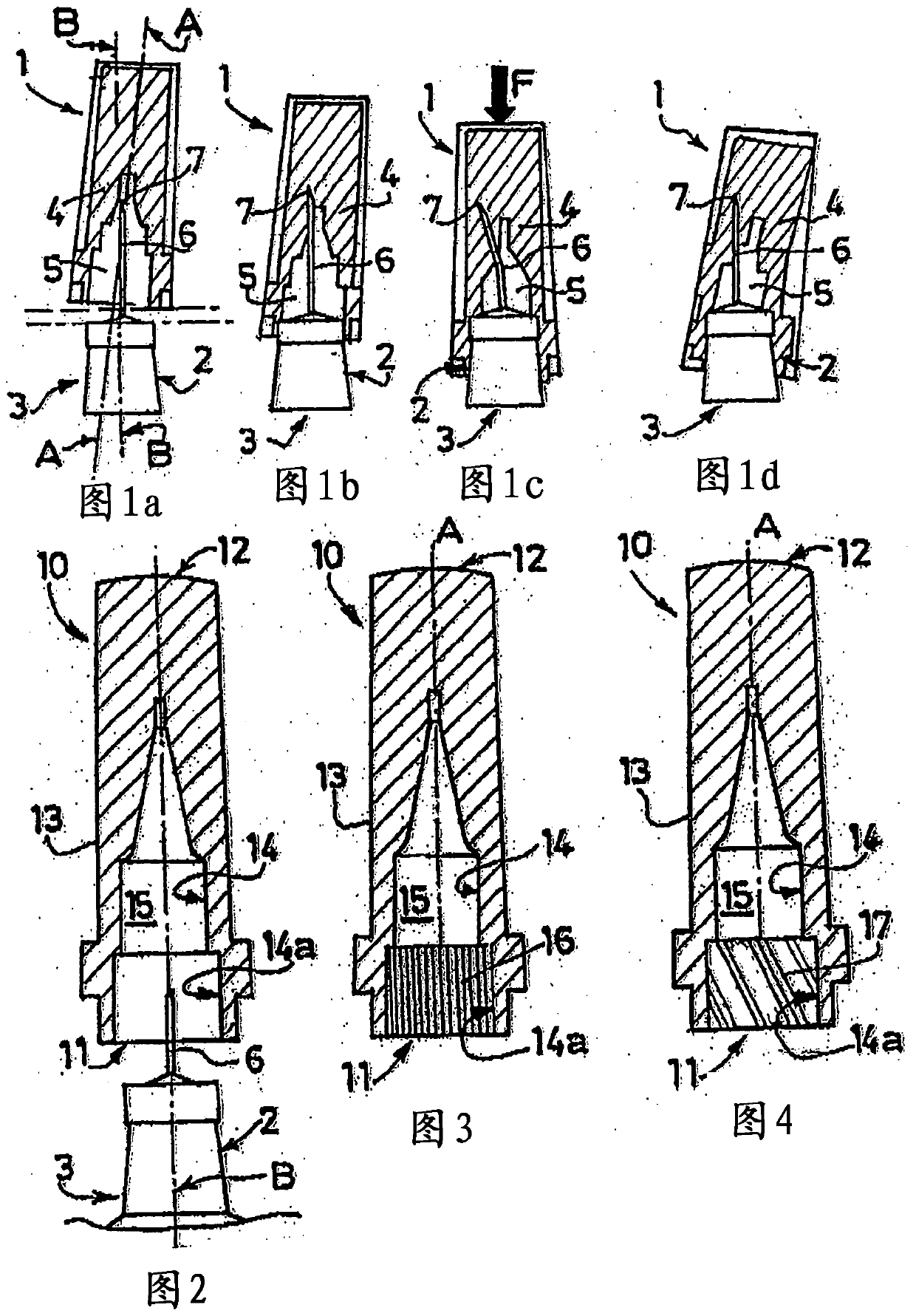
[0042] figure 2 A shroud 10 of the present invention is shown. Shield 10 is used to cover such as syringe 3 (in figure 2 The distal end of the drug delivery device shown partially in ). Alternatively, the drug delivery device may be a needle assembly. The distal end of the syringe 3 is provided with a hub 2 on which a needle 6 is secured. The shroud 10 has an open proximal end 11 , a closed distal end 12 and a wall 13 extending from said proximal end 11 to said closed distal end 12 . The inner surface 14 of the wall 13 forms a cavity 15 for receiving a part of the distal tip of the syringe 3 . When the shield 10 is fastened on the distal end of the syringe, a part 14a of the inner surface 14 is intended to contact the hub 2 of the distal end of the syringe 3 in order to protect the drug delivery device during transport, for example, before use. the distal end.

[0043] exist figure 2 wherein the average radial roughness of said portion 14a of the inner surface 14 of ...


PUM


Abstract

The invention relates to a guard (10) used at the tail end of the far side of a dosing device (3).The dosing device comprises a needle bed (2), the guard (10) with a wall (13) is used for being jointed on the needle bed in a removable manner, and an inner cavity (15) used for receiving the tail end of the dosing device (3) is limited by the inner surface (14) of the wall.When the guard (10) is jointed on the tail end of the dosing device (3), at least one part (14a) of the inner surface (14) of the wall is used for contacting with the needle bed (2) and has surface features (16 and 17) distributed on a main portion thereof, and the surface features limit contact quantity between the part (14a) and the needle bed (2).

Description

[0001] The present invention is a divisional application of the Chinese invention patent titled "needle shield with specific roughness" and application number 200780100551.3 (PCT / IB2007 / 003214, international filing date July 27, 2007). technical field [0002] The present invention relates to a shield for covering the distal tip of a drug delivery device at least prior to use of the drug delivery device. Background technique [0003] In the present application, the term distal refers to the part furthest from the user's hand and the term distal refers to the part closest to the user's hand. Likewise, in this application, the term "distal direction" refers to the direction of administration, ie towards the patient, while the term "proximal direction" refers to the direction opposite to the direction of administration, ie away from the patient. [0004] Drug delivery devices are commonly used in several technical fields, such as, for example, the field of medicine, for adminis...

Claims


Application Information

Patent Timeline
Patent Type & Authority Patents(China)
IPC IPC(8): A61M5/32
CPCA61M5/3202A61M5/321
Inventor J-C·蒂博J·贝尔纳
Owner BECTON DICKINSON FRANCE
Why Eureka
Try Eureka