Laser welding method of side electrode precious metal of spark plug

A laser welding and side electrode technology, applied in spark plug manufacturing and other directions, can solve the problems of uneven fusion at the welding place, affecting product quality, gaps and cracks, etc., to achieve uniform fusion, convenient welding, no gaps and cracks.

Active Publication Date: 2012-06-27
ZHUZHOU TORCH SPARK PLUG CO LTD
View PDF10 Cites 9 Cited by
  • Summary
  • Abstract
  • Description
  • Claims
  • Application Information

AI Technical Summary

Problems solved by technology

[0020] The purpose of the present invention is to propose a new side electrode laser for the problems that the existing side electrode noble metal laser welding often has uneven fusion, gaps and cracks, and uneven solder joints, which affect product quality. Welding method and device. The method and device can effectively solve the problems of uneven fusion, gaps and cracks, and uneven solder joints in side electrode laser welding, which affect product quality.

Method used


Image

  • Laser welding method of side electrode precious metal of spark plug
  • Laser welding method of side electrode precious metal of spark plug
  • Laser welding method of side electrode precious metal of spark plug

Examples


Embodiment 1

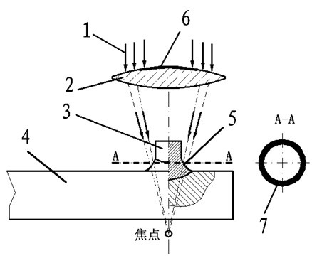
[0036] attached figure 1 As one embodiment of the present invention, it can be seen from the accompanying drawings that the present invention relates to a side electrode laser welding method, especially a laser welding method for a side electrode noble metal head through an annular laser spot emitted from above the noble metal head; The ring-shaped laser spot mentioned above can be condensed by a convex lens, and the direct laser light source that has not been fully focused is refracted by the convex lens so that the direction is gathered into a ring. The method of generating the ring beam is: emit a parallel downward laser beam 1 from the top of the side electrode noble metal head, the laser beam 2 passes through a convex lens 2 and then irradiates the root area 5 of the junction between the side electrode noble metal head 3 and the side electrode plate 4, and at the same time A circular light-shielding surface 6 is provided at the center of the convex lens 2, and the light-s...

Embodiment 2

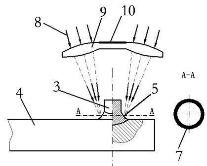
[0038] attached figure 2 As another embodiment of the present invention, it can be seen from the accompanying drawings that the present invention relates to a side electrode laser welding method, especially a laser welding method for the side electrode noble metal head through the annular laser spot emitted from above the noble metal head; The annular laser spot can also be condensed by a special-shaped lens, and the incident laser light source that has not been fully focused is refracted through the lens to make the direction converge into a ring. The method of generating the ring-shaped beam is: emit the laser beam 8 from above the side electrode noble metal head, the laser beam 8 passes through a special-shaped lens 9 and then irradiates to the root area 5 of the junction of the side electrode noble metal head 3 and the side electrode plate 4, and at the same time, the special-shaped lens 9 is provided with a circular lens shading surface 10, the lens shading surface 10 ca...

Embodiment 3

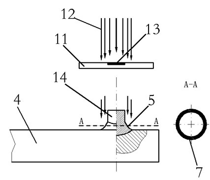
[0040] attached image 3 As another embodiment of the present invention, it can be seen from the accompanying drawings that the present invention relates to a side electrode laser welding method, especially a laser welding method for the side electrode noble metal head through the annular laser spot emitted from above the noble metal head; The ring-shaped laser spot can be formed by using a flat lens to block the converged laser beam to create a hollow in the middle of the beam. The method of generating the ring-shaped beam is: emit a parallel downward laser beam 11 from above the side electrode noble metal head, and the laser beam 11 passes through a flat lens 12 and then irradiates to the root region 5 of the junction between the side electrode noble metal head 3 and the side electrode plate 4, At the same time, a circular light-shielding surface 13 is provided at the center of the flat lens, and the light-shielding surface 13 can block part of the laser beam 11 emitted para...


PUM


Abstract

The invention discloses a laser welding method of side electrode precious metal of a spark plug. The laser welding method comprises the steps of: emitting a laser beam from the upside of a side electrode precious metal head, enabling the laser beam emitted from the upside of the side electrode precious metal head to keep clear a top region of the side electrode precious metal head through a lens to form an annular laser spot to irradiate a root region of a combining part o the side surface of the side electrode precious metal head and a side electrode plate; burning and melting a welding beamby using the annular laser spot, melting a material extruded through electric resistance welding, wherein a burning and melting region is shaped as a ring; and aligning a circle center of the annularlaser spot to a circle center of a rivet head, and irradiating a region to be welded by the laser spot after alignment. According to the invention, through adding the lens and arranging a shielding or reflecting region on the center of the lens for preventing laser from irradiating the top of the precious metal head, the laser irradiation manner is changed, the annular laser spot is formed for welding the precious metal head; and the annular laser spot is adopted to once form an annular region to be welded, and the annular region to be welded has the advantages of convenience for welding, uniform melting part, no gaps or cracks, and smooth welding surface.

Description

technical field [0001] The invention relates to a processing method of a metal component, in particular to a processing method of a spark plug side electrode; the method is mainly used for welding rivet head-shaped precious metals to the spark plug side electrode, and the welding place requires uniform fusion without Cracks and cracks, smooth solder joints. Background technique [0002] Laser welding belongs to fusion welding, which uses laser beam as energy source and impacts on the weldment joint. The laser beam can be directed by planar optics, such as mirrors, and then reflective focusing elements or mirrors project the beam onto the weld seam. Focused energy melts the metals on both sides of the weld and fuses them together to achieve the purpose of welding. Laser welding is non-contact welding. No pressure is required during the operation, but inert gas is required to prevent oxidation of the molten pool. Filler metals may also be added. [0003] Laser welding has ...

Claims


Application Information

Patent Timeline
Patent Type & Authority Applications(China)
IPC IPC(8): H01T21/02
Inventor 谢菊泉陈件明陈小双
Owner ZHUZHOU TORCH SPARK PLUG CO LTD
Why Eureka
Try Eureka