Pipe welding machine

A technology for pipe fitting welding and welding mechanism, applied in welding equipment, welding equipment, auxiliary welding equipment, etc., can solve the problems of inability to take out pipe fittings, inconvenient for large-scale use, and low efficiency.

Active Publication Date: 2016-06-01
绩溪徽腾机械有限公司
View PDF5 Cites 9 Cited by
  • Summary
  • Abstract
  • Description
  • Claims
  • Application Information

AI Technical Summary

Problems solved by technology

[0003] The welding machine in the prior art cannot take out the pipe fittings after welding, and the pipe fittings can only be taken out by opening the shell, which is not only inefficient, but also inconvenient for large-scale use in production

Method used


Image

  • Pipe welding machine
  • Pipe welding machine

Examples


Embodiment Construction

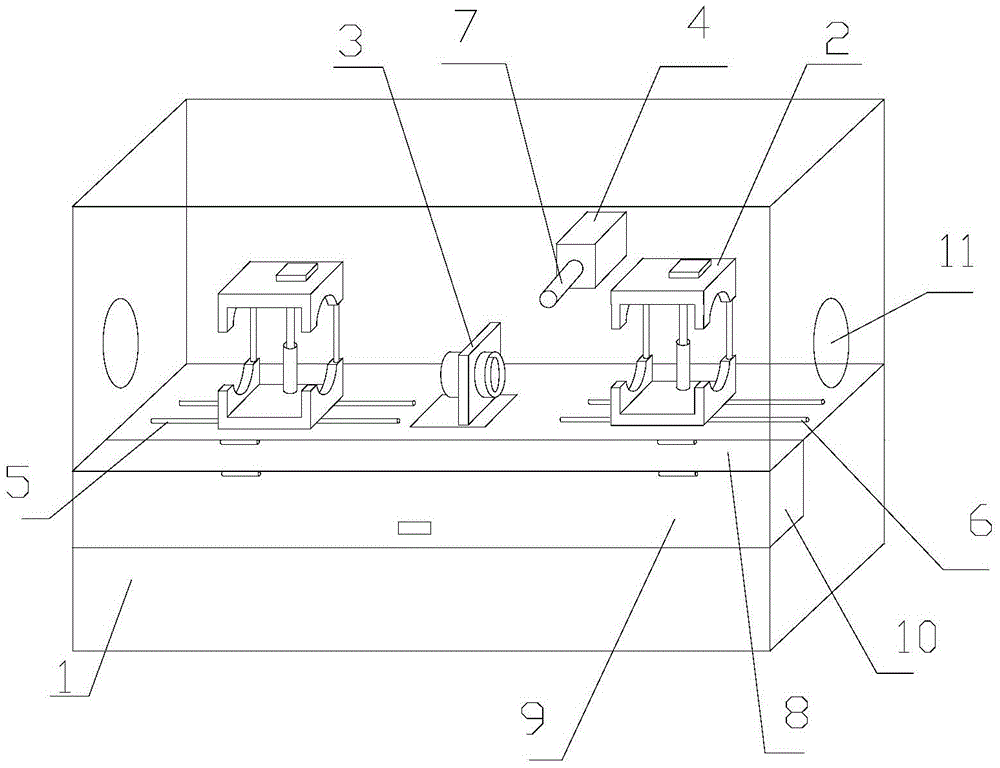
[0030] Specific embodiments of the present invention will be described in detail below in conjunction with the accompanying drawings. It should be understood that the specific embodiments described here are only used to illustrate and explain the present invention, and are not intended to limit the present invention.

[0031] In the present invention, unless stated otherwise, the used orientation words such as "up, down, left, right" usually refer to figure 1 Up and down and left and right are shown. "Inner and outer" refer to the inner and outer on the specific outline. "Far and near" refer to far and near relative to a certain component.

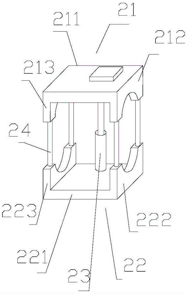
[0032] The present invention provides a pipe fitting welding machine, which includes: a base 1, a welding mechanism, a cylinder 4, a push rod 7 and a casing, the casing is arranged on the upper surface of the base 1 and forms a working chamber, The working chamber can be used to realize the welding work; the welding mechanism is arrange...


PUM


Abstract

The invention discloses a pipe welding machine. The pipe welding machine comprises a base (1), a welding mechanism, an air cylinder (4), an ejector rod (7) and an outer shell. The outer shell is arranged on the upper surface of the base (1) and forms a working cavity. The welding mechanism is arranged on the upper surface of the base (1). The air cylinder (4) is fixedly connected to the outer shell and arranged on one side of the welding mechanism. A piston rod of the air cylinder (4) moves in the length direction and is connected to one end of the ejector rod (7) and coaxial with the ejector rod (7). The other end of the ejector rod (7) faces a pipe. A groove cavity (10) used for containing the pipe is formed in the other side, opposite to the air cylinder (4), of the base (1). The pipe welding machine overcomes the defect that pipes cannot be taken out after being welded through welding machines in the prior art, and automatic ejection of the welded pipe is achieved.

Description

technical field [0001] The invention relates to the field of welding of multiple pipe fittings, in particular to a pipe fitting welding machine. Background technique [0002] In the existing technology, due to the limitation of equipment, when long pipes are required in the field with high sealing requirements, it is often not successful in one-time injection molding, but needs to be welded to form a long pipe, and the purpose of welding is of course It is to be sealed, the tighter the welding, the better the sealing effect. [0003] The welding machine in the prior art cannot take out the pipe fittings after welding, and the pipe fittings can only be taken out by opening the shell, which is not only inefficient, but also inconvenient for large-scale use in production. Contents of the invention [0004] The object of the present invention is to provide a pipe fitting welding machine, which overcomes the inability of the welding machine in the prior art to take out the pip...

Claims


Application Information

Patent Timeline
Patent Type & Authority Applications(China)
IPC IPC(8): B23K31/02B23K37/00
CPCB23K31/027B23K37/00
Inventor 胡德华
Owner 绩溪徽腾机械有限公司
Why Eureka
Try Eureka