Diamond tool bit bevel face grinding device

A diamond cutter head, grinding technology, applied in the direction of grinding drive device, grinding machine parts, grinding/polishing equipment, etc., can solve the problems of low production efficiency, unable to meet social needs, etc. Compact structure and stable performance

Active Publication Date: 2016-06-01
鄂州市通磊超硬材料有限公司
View PDF6 Cites 7 Cited by
  • Summary
  • Abstract
  • Description
  • Claims
  • Application Information

AI Technical Summary

Problems solved by technology

Machining includes grinding the bottom surface, grinding the bevel and grinding the edges and corners; at present, all machining can only manually clamp the diamond cutter head on the corresponding fixture, and then use the machine tool for grinding; this processing method obviously has low production efficiency and cannot meet the requirements. social needs

Method used


Image

  • Diamond tool bit bevel face grinding device
  • Diamond tool bit bevel face grinding device
  • Diamond tool bit bevel face grinding device

Examples


Embodiment 1

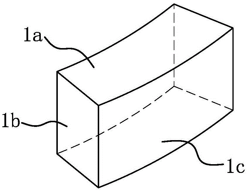
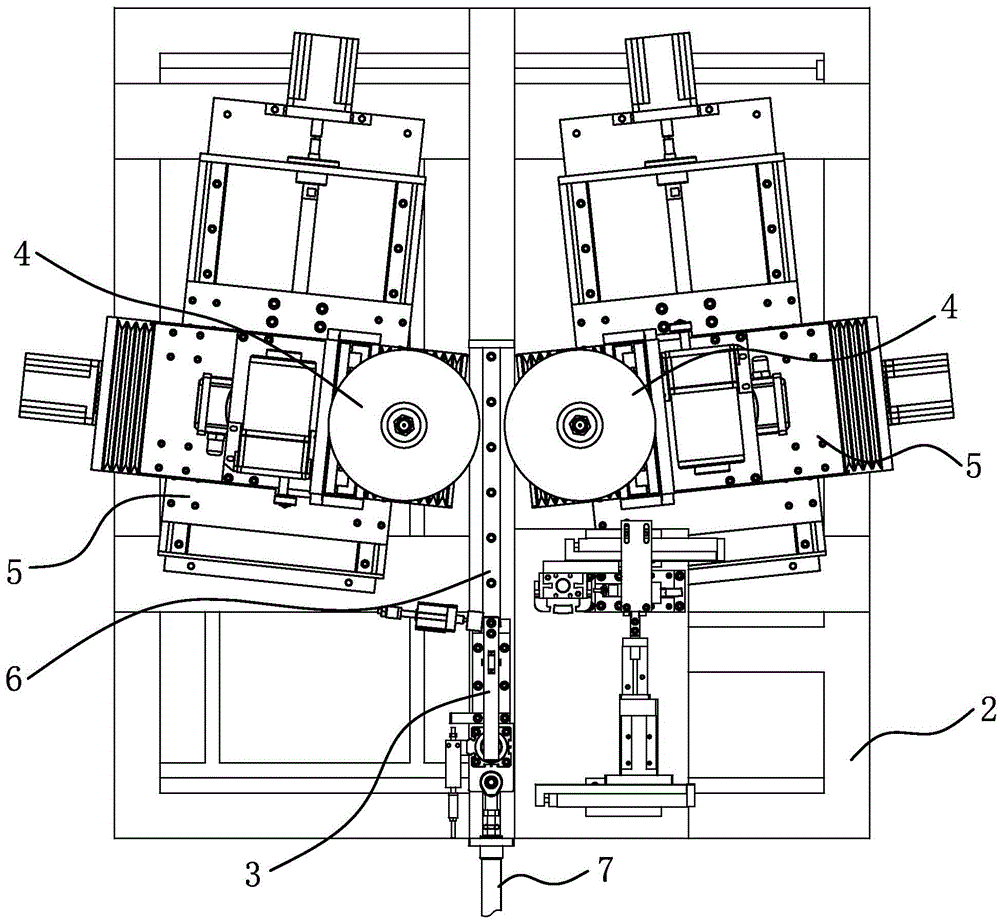
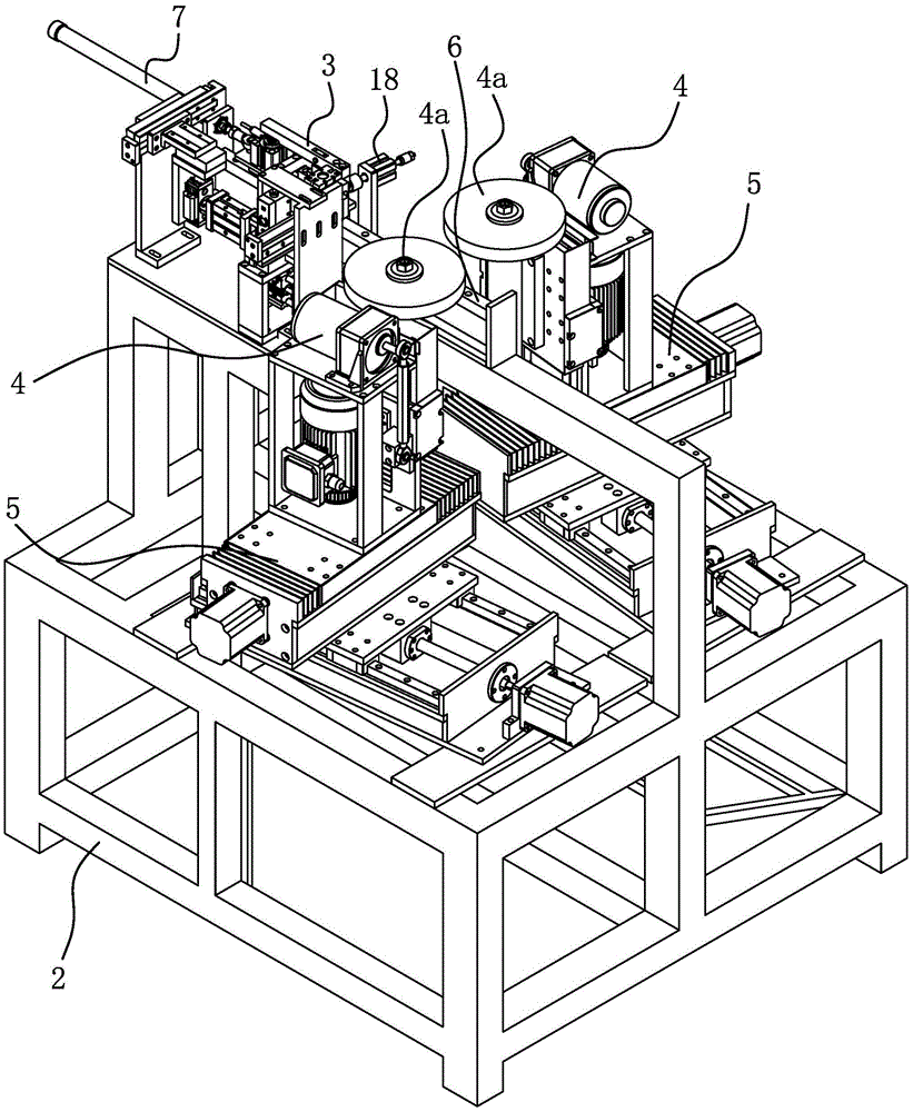
[0036] The grinding device for the beveled surface 1b of the diamond segment includes a frame 2 , a clamp 3 , a grinding mechanism 4 and a feeding mechanism 5 .

[0037] The clamp 3 is arranged on the frame 2 for clamping the diamond segment 1 . In order to facilitate grinding, after the diamond cutter head 1 is clamped, the cutter face of the diamond cutter head 1 faces upward, the bottom face faces, the inner face faces outward, and the two slopes 1b are located outside the fixture 3 . In order to improve the positioning accuracy, the bottom surface of the diamond segment 1 has been machined by grinding. The fixture 3 includes a base 3a, on which a support block 3b for supporting the bottom surface of the diamond cutter head 1 is fixed, on which a pressure rod 3c is hinged, and one end of the pressure rod 3c is connected with a pressure rod for mortgaging the diamond blade surface. block; the base 3a is inherently connected to the other end of the pressure rod 3c and can ma...

Embodiment 2

[0049] Compared with the present embodiment, the difference lies in that the base 3a of the clamp 3 is fixed on the frame 2; other structures are the same, and will not be repeated here.

Embodiment 3

[0051] Compared with the first embodiment, this embodiment also has the following structure: the frame 2 is provided with a fifth linear guide rail 8 perpendicular to the fourth linear guide rail 6, and the slider of the fifth linear guide rail 8 is provided with a first pneumatic clamp Head 9, the frame 2 is provided with the feeding cylinder 10 that is connected with the first pneumatic chuck 9 and can drive the first pneumatic chuck 9 to move; between the third drive assembly 7 and the base 3a of the clamp 3, there is a The gripper 3 avoids the escape cylinder 11 of the movement track of the first pneumatic chuck 9 , and the third drive assembly 7 and the gripper 3 are connected through the avoidance cylinder 11 .

[0052] The diamond segment 1 is first clamped by the first pneumatic chuck 9 . Specifically, the first pneumatic chuck 9 is clamped on the two slopes 1 b of the diamond bit 1 . In order to put the diamond bit 1 clamped by the first pneumatic chuck 9 into the cl...


PUM


Abstract

The invention provides a diamond tool bit bevel face grinding device and belongs to the field of an operation technology. The diamond tool bit bevel face grinding device solves the problem that existing diamond tool bit bevel face grinding is conducted through a general-purpose machine tool, and production efficiency is low. The diamond tool bit bevel face grinding device comprises a rack and a clamp used for clamping a diamond tool bit and arranged on the rack. The outer sides, relative to two bevel faces of the clamped diamond tool bit, of the clamp are each provided with a grinding mechanism with a grinding wheel. A feeding mechanism making the corresponding grinding wheel fed in parallel along the corresponding target bevel face is arranged between each grinding mechanism and the rack. By the adoption of the diamond tool bit bevel face grinding device, the bevel faces of the diamond tool bit are fed and ground automatically, the two bevel faces are machined at the same time, and the diamond tool bit bevel face grinding device has the beneficial effect of being high in production efficiency; and the grinding wheels of the diamond tool bit bevel face grinding device can be fed automatically after grinding is shrunk gradually, and the diamond tool bit bevel face grinding device has the beneficial effects of being high in production efficiency and capable of guaranteeing grinding accuracy.

Description

technical field [0001] The invention belongs to the field of operation technology, and relates to a grinding device, in particular to a diamond cutter head bevel grinding device. Background technique [0002] The diamond segment is the working body of the diamond saw blade. The cutter head of the diamond saw blade is composed of diamond and matrix binder. Diamond is a superhard material that acts as a cutting edge, and the matrix binder acts as a fixed diamond. [0003] like figure 1 Shown is a diamond cutter head for a thin-walled drill. The diamond cutter head has two end surfaces, two inclined surfaces, an inner surface and an outer surface 1c, and the intersection line between the outer surface 1c and the inclined surfaces is an angle; if one end has diamond, the end surface is the cutter surface, and the other end surface is the bottom surface. [0004] The diamond cutter head is first produced by hot pressing to obtain a blank, and then processed to obtain a qualifi...

Claims


Application Information

Patent Timeline
Patent Type & Authority Applications(China)
IPC IPC(8): B24B9/16B24B3/60B24B47/20
CPCB24B3/60B24B9/16B24B9/161B24B47/20
Inventor 项大清
Owner 鄂州市通磊超硬材料有限公司
Why Eureka
Try Eureka