Aircraft cylinder heading installation structure

A technology for installing structures and gas cylinders, which is applied to aircraft parts, mechanical equipment, transportation and packaging, etc. It can solve the problems of general layout restrictions, difficulty in regular inspection and maintenance, and gas leakage, so as to improve maintainability and safety, and facilitate daily life Maintenance work, convenient disassembly and inspection effect

Active Publication Date: 2018-07-06
XIAN AIRCRAFT DESIGN INST OF AVIATION IND OF CHINA
View PDF4 Cites 0 Cited by
  • Summary
  • Abstract
  • Description
  • Claims
  • Application Information

AI Technical Summary

Problems solved by technology

[0002] Aircraft gas cylinders are traditionally installed in the form of transverse direction gas cylinders perpendicular to the direction of the aircraft, and clamps are used for limit restraint. This form will inevitably make one end of the gas cylinder far away from the mouth cover, due to the dense equipment arrangement. It is difficult to disassemble and assemble the gas cylinders, and it is difficult to check and maintain them regularly. Due to the complex aircraft equipment and limited space, sometimes it cannot meet the installation and layout requirements of the horizontal direction, which also brings great restrictions to the overall layout.
For installation along the course, it is more difficult to fix the gas cylinder along the axial direction due to the large overload of the aircraft course, and the overload causes the gas cylinder to move along the course or the connection between the gas cylinder interface and the aircraft pipeline is relatively shaken, causing gas leakage

Method used


Image

  • Aircraft cylinder heading installation structure
  • Aircraft cylinder heading installation structure
  • Aircraft cylinder heading installation structure

Examples


Embodiment

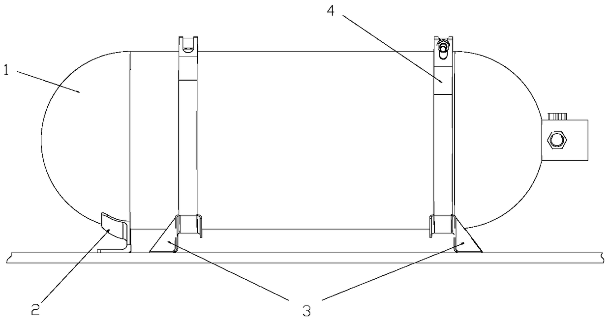
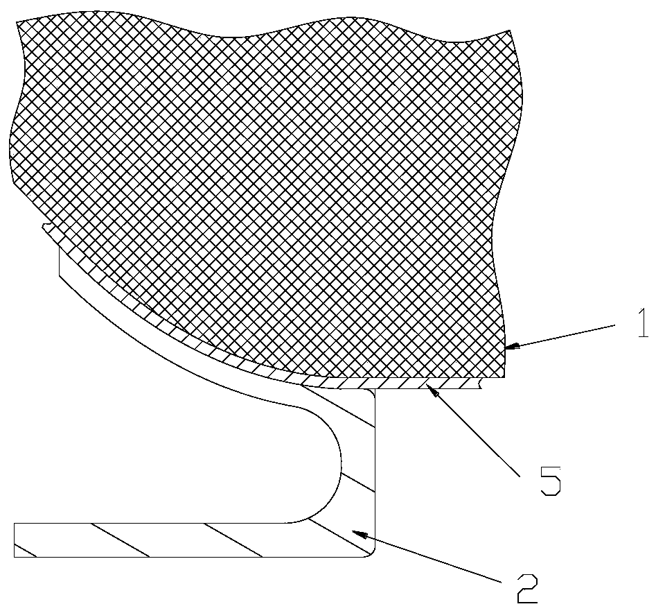
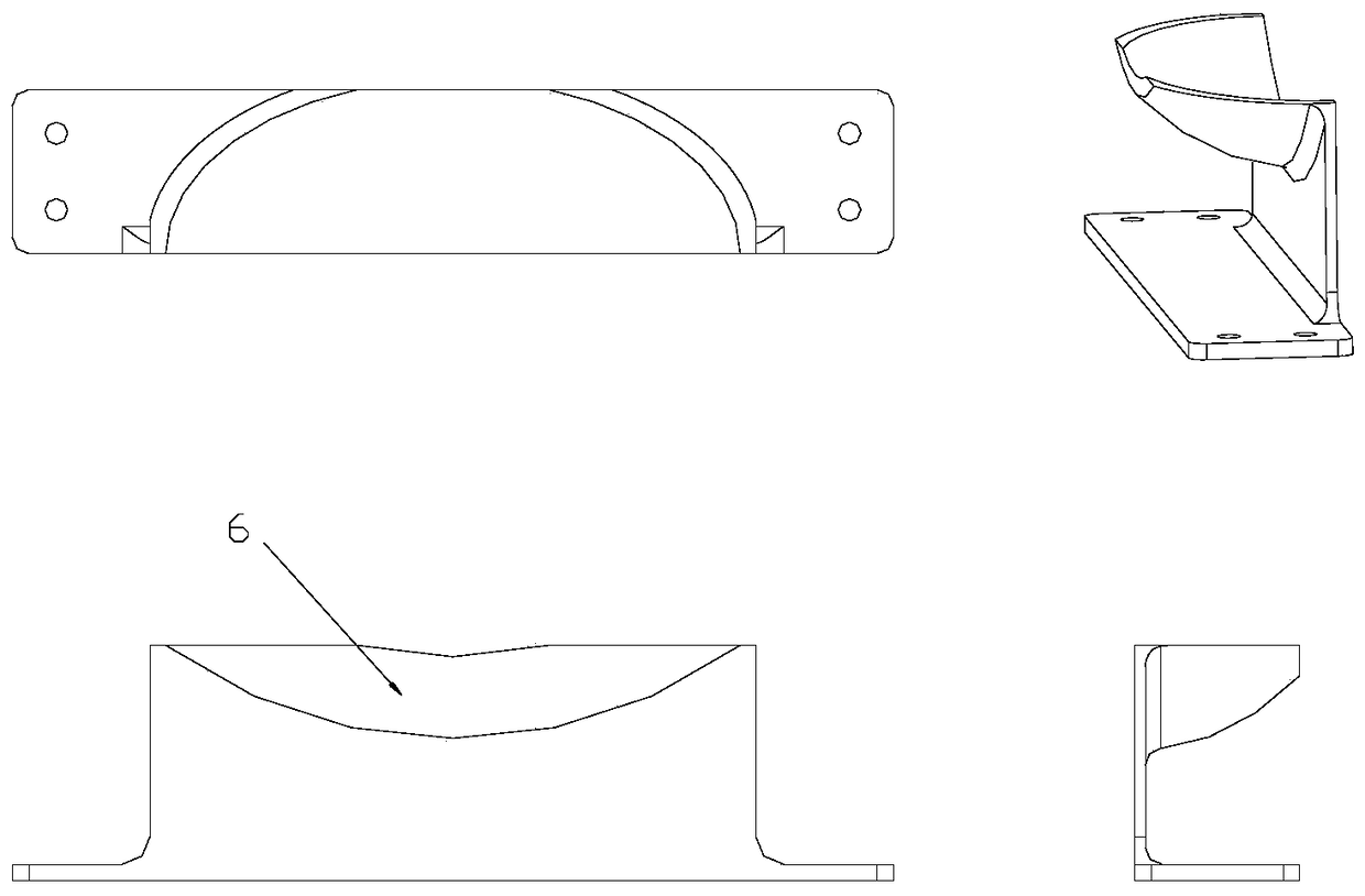
[0017] see Figure 1-Figure 4 , an aircraft gas cylinder heading installation structure, which is composed of a gas cylinder 1, a base 2, a bottom bracket 3, a clamp 4, and a buffer pad 5. The neck and bottom of the cylinder 1 are clamped by the clamp 4 to prevent their displacement. The gas cylinder 1 is limited by the base 2 to prevent its axial displacement under large overload, and the clamp 4 and the bottom bracket 3 are connected together by riveting; Use HB7792-2005J glue or other adhesive with similar performance to stick the buffer pad 5 on the clamp 4, and allow thickening of the buffer pad 5 during installation to ensure that the gas cylinder 1 is closely attached; use XY401 / HB7792-2005J glue or performance The buffer pad 5 is bonded to the base 2 by other adhesives that are close to it, and the buffer pad 5 is allowed to be thickened to ensure that the gas cylinder 1 is in close contact with it during installation.

[0018] There is a buffer pad 5 between the base...


PUM


Abstract

The invention belongs to the technique of design of mechanical systems of aircrafts and relates to a heading installation structure for a gas cylinder of an aircraft. The heading installation structure for the gas cylinder of the aircraft is composed of the gas cylinder (1), a base (2), two bottom supports (3), two clamps (4) and cushions (5). The neck and the bottom of the gas cylinder (1) are clamped through the clamps (4), so that displacement of the neck and the bottom of the gas cylinder (1) is prevented. The gas cylinder (1) is limited through the base (2), so that axial displacement of the gas cylinder (1) under a high overload condition is prevented. The clamps (4) and the bottom supports (3) are connected in a riveted mode. The cushions (5) adhere to the clamps (4) and the base (2) correspondingly. The supporting surface on the base (2) is in the shape of a two-dimensional curved surface and is in complete fit with the appearance of the gas cylinder (1). By the adoption of the heading installation structure for the gas cylinder of the aircraft, the effect that the gas cylinder can be firmly retrained on a supporting base under the high overload condition during landing and the like of the aircraft is guaranteed, and high overload protection for heading installation of the gas cylinder of the aircraft is achieved; the problem that according to a traditional clamp form, the stability of the gas cylinder cannot be guaranteed during heading installation of the gas cylinder is solved, and the maintainability and safety of the gas cylinder are effectively improved.

Description

technical field [0001] The invention belongs to the design technology of an aircraft mechanical system, and relates to an installation design method of an aircraft air cylinder. Background technique [0002] Air cylinders for aircraft are traditionally installed in the form of transverse course cylinders axially perpendicular to the aircraft heading, and clamps are used to limit the position. It is difficult to disassemble and assemble gas cylinders, and it is difficult to regularly inspect and maintain them. Because of the complex equipment and limited space of the aircraft, sometimes it cannot meet the installation and layout requirements in the lateral direction, which also brings great restrictions to the overall layout. For the installation along the course, it is more difficult to fix the gas cylinder in the axial direction due to the large overload of the aircraft heading. Due to the overload, the gas cylinder moves along the heading or the connection between the gas ...

Claims


Application Information

Patent Timeline
Patent Type & Authority Patents(China)
IPC IPC(8): B64D47/00F17C13/08
Inventor 李国栋窦田天王莉
Owner XIAN AIRCRAFT DESIGN INST OF AVIATION IND OF CHINA
Why Eureka
Try Eureka