A piezoelectric sounding structure and mobile terminal

A sounding structure and mobile terminal technology, applied in the field of speakers, can solve the problems of weak sounding, short circuit of piezoelectric ceramic speakers, unreliable welding, etc., and achieve the effects of good piezoelectric deformation conduction, improved sounding effect, and simple and reliable structure.

Active Publication Date: 2017-12-26
KINGTONE INNOVATION BEIJING TECH
View PDF6 Cites 0 Cited by
  • Summary
  • Abstract
  • Description
  • Claims
  • Application Information

AI Technical Summary

Problems solved by technology

The following problems usually occur when piezoelectric ceramics and their metal substrates are combined with the housing: when the piezoelectric ceramics and its metal substrates are combined with the housing, the bonding will not be firm when the piezoelectric ceramics and its metal substrates are bonded with the housing, and the metal diaphragm will vibrate locally unbalanced And other problems, which lead to the reduction of the sound pressure sensitivity of the entire sound system; the positive and negative signal lines are directly welded on the piezoelectric ceramic sheet, and there are often phenomena such as poor welding and excessive solder joint volume, which will short-circuit or open the piezoelectric ceramic speaker. and unable to work; or unreliable welding leads to damage to the piezoelectric ceramic speaker, etc.
[0004] On the other hand, in many existing designs of piezoelectric speakers, a single piece of piezoelectric ceramic is generally used to directly push the air through deformation to produce sound; since the deformation of piezoelectric ceramic is generally small, if the ceramic area is small, the sound will It is extremely weak and cannot be compared with traditional speakers; if the ceramic area is large, it is difficult to apply in batches because of the complex process, low yield and high cost

Method used


Image

  • A piezoelectric sounding structure and mobile terminal
  • A piezoelectric sounding structure and mobile terminal
  • A piezoelectric sounding structure and mobile terminal

Examples


Embodiment 1

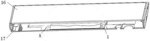
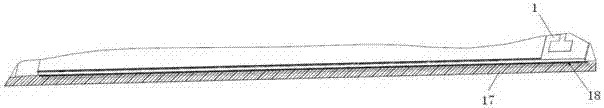
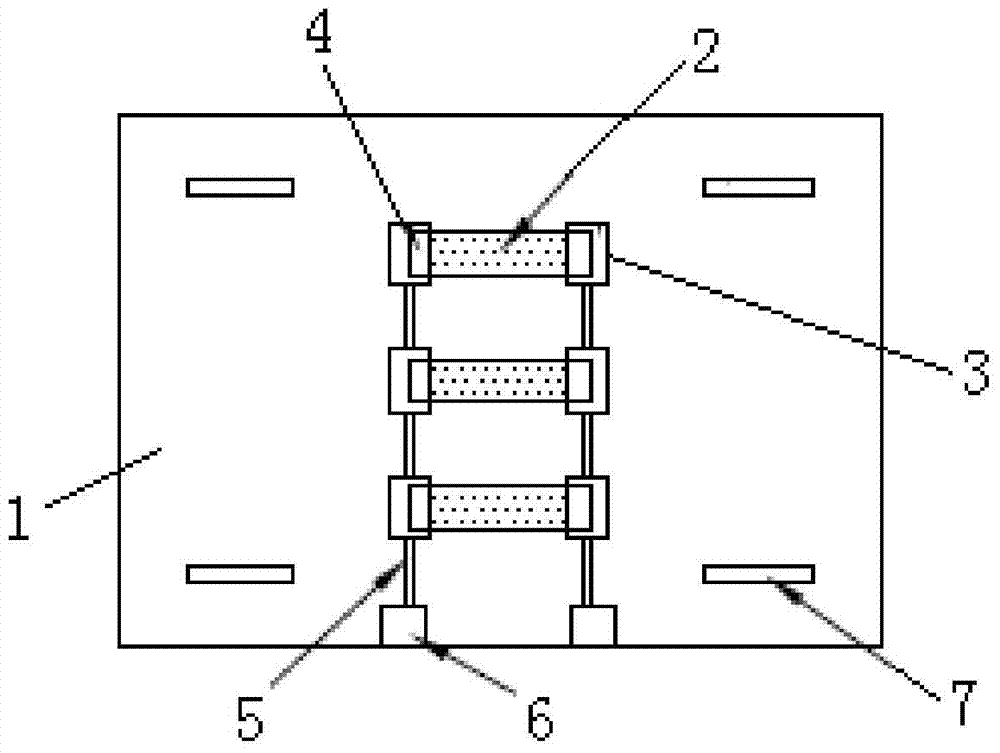
[0042] This embodiment provides a piezoelectric sound generating structure, such as figure 1 with figure 2 As shown, the piezoelectric sound generating structure includes a PCB board 1 and three piezoelectric ceramics 2 tightly coupled to the front surface of the PCB board 1. The PCB board 1 is provided with copper foil pads 3, solder joints 4, signal copper foil wires 5 and signal input pads 6 corresponding to three piezoelectric ceramics 2 respectively. The signal copper foil wire 5 inputs the signal to the pads 6 and the copper foil pad 3 are connected in sequence. The PCB board 1 is also provided with tuning holes / slots 7 for adjusting the vibration mode. The tuning holes / slots 7 can be single or multiple. The tuning holes / slots 7 can be round, square, or oval. 形等。 Shape and so on. By changing the number, shape, and arrangement of the tuning holes / slots 7, the mechanical deformation mode of the PCB board 1 can be adjusted, thereby optimizing the acoustic curve and optimizi...

Embodiment 2

[0048] This embodiment provides a piezoelectric sound generating structure, such as Figure 5 As shown, it adopts a double-sided mounting process on the basis of Embodiment 1. The upper and lower sides of the PCB board 1 are respectively provided with pads, which are a surface pad 8 and a bottom pad 9, respectively. The surface pad 8 and the bottom pad 9 are respectively provided with a surface layer piezoelectric ceramic sheet 10 and a bottom layer piezoelectric ceramic sheet 11 respectively. The ceramic end electrodes of the piezoelectric ceramic sheets on both sides are closely connected with the pads on both sides of the PCB board through a welding process.

[0049] Since the piezoelectric sound generating structure of this embodiment is provided with piezoelectric ceramics on both sides of the PCB board, it can effectively enhance the mechanical vibration driving effect and greatly improve the sound pressure output.

[0050] Among them, the piezoelectric ceramic in this embodi...

Embodiment 3

[0052] This embodiment provides a piezoelectric sound generating structure, such as Image 6 As shown, the structure is basically the same as that of the first embodiment, including a PCB board 1 and a piezoelectric ceramic 2 tightly coupled to the PCB board 1. The difference is that in this embodiment, the piezoelectric drive chip 12 (such as TI's TPA2100P1) is directly integrated on the PCB board 1, so that the piezoelectric drive circuit 13 can be shortened and the EMI noise of the circuit can be reduced; while the piezoelectric element Unlike traditional moving coil speakers, it does not contain electromagnetic components and basically does not produce EMI noise. At the same time, for different piezoelectric elements, the drive circuit can be directly configured to the optimal drive parameters (impedance characteristic matching, frequency characteristic correction), truly realizing the plug and play function.


PUM


Abstract

The invention discloses a piezoelectric sounding structure and a mobile terminal, and relates to the technical field of loudspeakers. The piezoelectric sounding structure includes a PCB board and at least one piezoelectric ceramic tightly bonded to the PCB board. The piezoelectric ceramic is used to generate mechanical deformation through the inverse piezoelectric effect under the drive of the drive circuit. The tightly bonded PCB generates controlled mechanical vibration; and the vibration is transmitted by the PCB or the outer shell of the terminal device tightly bonded with the PCB and further pushes the air to generate sound. The present invention also proposes a mobile terminal having the above-mentioned piezoelectric sounding structure, the inner side of the housing of which is closely combined with the piezoelectric sounding structure mentioned in the present invention. The piezoelectric sounding structure provided by the present invention can greatly improve the sound radiation efficiency because the entire PCB board or the outer casing of the terminal structure can radiate sound waves, and can reduce the volume of the sounding structure while ensuring the volume and sound effect.

Description

Technical field [0001] The present invention relates to the technical field of loudspeakers, and in particular to a piezoelectric sound generating structure and a mobile terminal having the piezoelectric sound generating structure. Background technique [0002] With the development of portable consumer electronics, people’s requirements for small and thin portable electronic devices are getting higher and higher. Piezoelectric ceramic speakers are gradually being used by many portable consumer electronic products due to their ultra-light, ultra-thin, high-efficiency, and no need for large sound chambers. Favored. Portable consumer products are developing in the direction of ultra-thin, light-weight and small. Such system requirements put forward requirements for thinner, smaller, and more power-saving single electronic components. Piezoelectric ceramic speakers are used in more and more places because of their small, thin, light, and compact packaging. [0003] The basic principl...

Claims


Application Information

Patent Timeline
Patent Type & Authority Patents(China)
IPC IPC(8): H04R17/00
Inventor 张韬袁世明
Owner KINGTONE INNOVATION BEIJING TECH
Why Eureka
Try Eureka