
Fan lamp

A technology for fan lamps and lampshades, which is applied to cooling/heating devices of lighting devices, lighting and heating equipment, mechanical equipment, etc., and can solve problems that affect the aesthetics of fan lamps, are not conducive to human eye health, and cannot be converted into other structural forms.

Inactive Publication Date: 2016-06-01
JIANGMEN LINGFENG ELECTRONICS APPLIANCE CO LTD
View PDF4 Cites 1 Cited by
  • Summary
  • Abstract
  • Description
  • Claims
  • Application Information

AI Technical Summary

Problems solved by technology

However, the light distribution method of the existing fan lamp is relatively traditional and single. Since the fan blade structure of the fan lamp is located above the light source structure, if the light source shines upward, the light will be dazzling when it shines on the rotating fan blade, and the light output effect is very good. Poor and not conducive to the health of human eyes, therefore, the light source is generally set in the form of downward irradiation, the structural design and light distribution design of the light source are single and rigid, and cannot be converted into other structural forms. People can directly see the light source, which affects the aesthetics of the fan lights. Moreover, it is easy to cause glare due to direct viewing of the light source. With the improvement of people's living standards, the existing fan lights can no longer satisfy the majority of consumers. increasing demand

Method used


Image

  • Fan lamp
  • Fan lamp
  • Fan lamp

Examples


Embodiment Construction

[0019] It should be understood that the specific embodiments described here are only used to explain the present invention, not to limit the present invention.

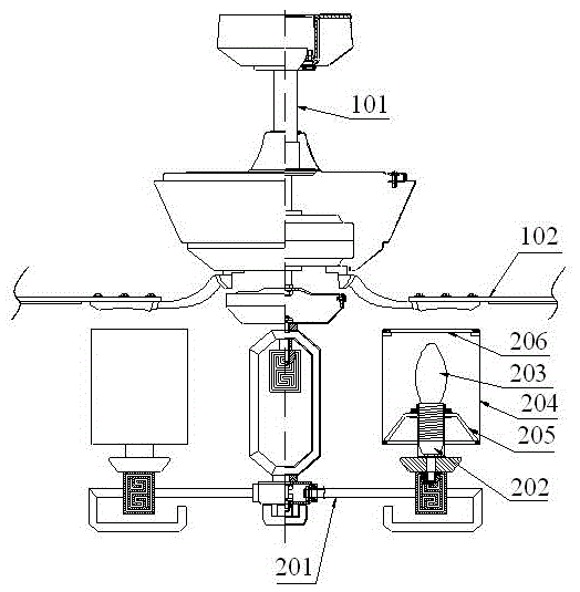
[0020] refer to Figure 1 to Figure 5 , an embodiment of a fan lamp of the present invention is proposed, which includes a fan lamp main body. The fan lamp main body includes a central axis column 101, a motor installed on the central axis column 101, and is installed on the central axis column 101 and can be operated with the motor. Rotating blade structure 102 .

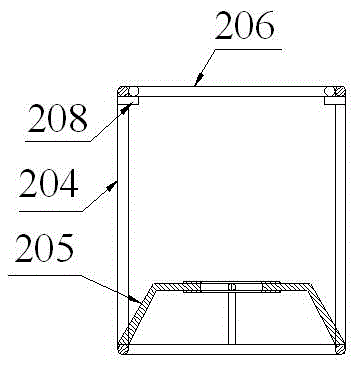
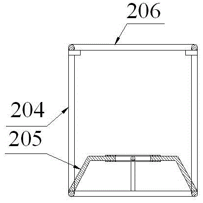
[0021] The fan lamp also includes a lamp body structure installed on the central axis column 101 and located below the fan blade structure 102. The lamp body structure includes a number of lamp arms 201 installed on the central axis column 101 and located below the fan blade structure 102. The lamp holder structure 202 on the arm 201 , the light source structure 203 mounted on the upper end of the lamp holder structure 202 and illuminating upward and side...


PUM


Abstract

The invention discloses a fan lamp. The fan lamp comprises a fan lamp body; the fan lamp body includes a center shaft column, a motor arranged on the center shaft column, and a blade structure mounted on the center shaft column and capable of rotating along with the motor. The fan lamp further comprises a lamp body structure mounted on the center shaft column and positioned below the blade structure; the lamp body structure includes multiple lamp arms mounted on the center shaft column and positioned below the blade structure, a lamp holder structure arranged on the lamp arms, a light source structure mounted at the upper end of the lamp holder structure and irradiating to the upper side and the side surface, and a lamp cover structure covering the light source structure; the lamp cover structure includes a side frame cover surrounding the outer side surface of the light source structure, a mounting frame mounted in the side frame cover, and a lamp cover covering the upper end of the side frame cover; a reflecting layer is arranged on the lower end surface of the lamp cover; and the lamp cover can be set as an embedded structure or an external structure or a closed fixed structure.

Description

technical field [0001] The invention relates to the technical field of lamps, in particular to a fan lamp. Background technique [0002] Lamps are indispensable lighting appliances in interior decoration. With the improvement of people's living standards, there are more and more types of lamps. Among them, fan lamps are more and more widely used because of their dual functions of lighting and fans. However, the light distribution method of the existing fan lamp is relatively traditional and single. Since the fan blade structure of the fan lamp is located above the light source structure, if the light source shines upward, the light will be dazzling when it shines on the rotating fan blade, and the light output effect is very good. Poor and not conducive to the health of human eyes, therefore, the light source is generally set in the form of downward irradiation, the structural design and light distribution design of the light source are single and rigid, and cannot be conver...

Claims


Application Information

Patent Timeline
IPC IPC(8): F21S8/00F21V7/22F21V29/83F21V33/00F04D25/08F21Y115/10
CPCF21S8/00F04D25/088F21V7/22F21V29/83F21V33/0044
Inventor 叶炳苏
Owner JIANGMEN LINGFENG ELECTRONICS APPLIANCE CO LTD
Learn More