
Optical assembly and illuminating device with same

A technology of optical components and light surfaces, applied in lighting devices, fixed lighting devices, components of lighting devices, etc., can solve problems such as bright spots in the center of optical components, achieve the effect of reducing the phenomenon of yellow circles and improving the utilization rate of light

Inactive Publication Date: 2016-06-01
DONGGUAN LEDLINK OPTICS +2
View PDF5 Cites 3 Cited by
  • Summary
  • Abstract
  • Description
  • Claims
  • Application Information

AI Technical Summary

Problems solved by technology

[0005] One object of the present invention is to provide an optical component and a lighting device with the optical component, by providing several microstructures with curved surfaces on at least the ring of the light incident surface, so as to reduce the phenomenon of yellow circles and improve the utilization of light efficiency and solve the problem of optical components causing the central bright spot

Method used


Image

  • Optical assembly and illuminating device with same
  • Optical assembly and illuminating device with same
  • Optical assembly and illuminating device with same

Examples


Embodiment Construction

[0060] The technical solutions in the embodiments of the present invention will be clearly and completely described below in conjunction with the drawings in the embodiments of the present invention, but the described embodiments are only some of the embodiments of the present invention, not all of them. In addition, in order to facilitate description or understanding of the present invention, similar or identical components herein use the same or similar component symbols in different drawings or different embodiments.

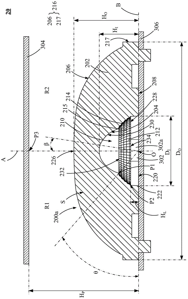
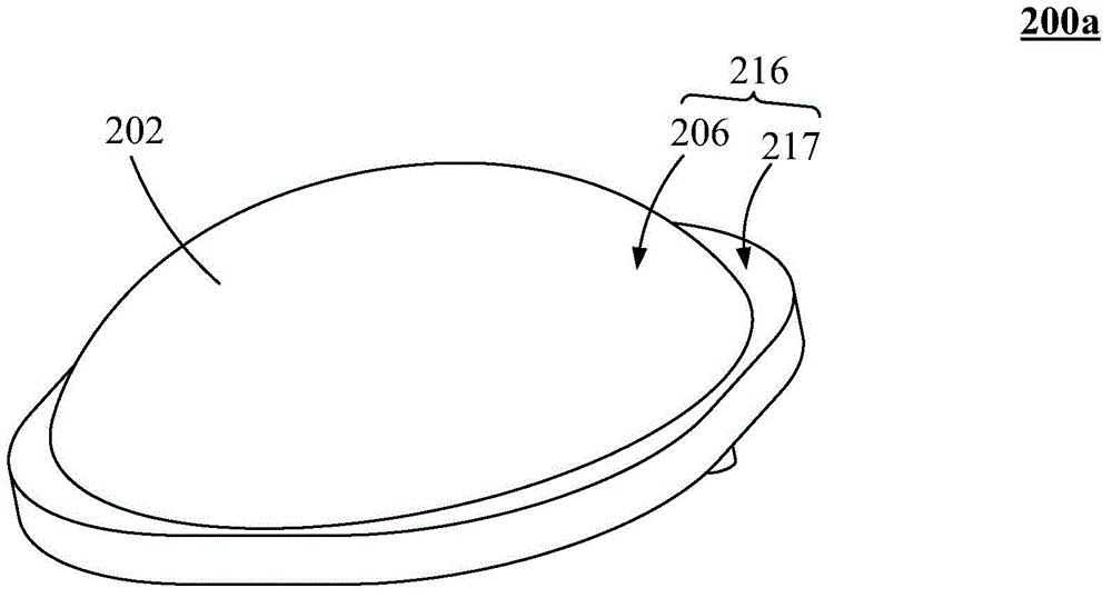
[0061] Please refer to Figure 2 to Figure 4 shown, where figure 2 It is a cross-sectional view of a lighting device 20 according to an embodiment of the present invention. image 3 is to draw figure 2 A schematic perspective view of the optical assembly 200a in . Figure 4 is to draw figure 2 A partial perspective side view of the optical assembly 200a in . As in the 2nd to Figure 4 As shown, in one embodiment, the lighting device 20 includes an op...


PUM


Abstract

The invention discloses an optical assembly and an illuminating device. The optical assembly comprises a body, a light entering surface and a light exiting surface. Concave space is formed in the bottom of the body. The light entering surface is defined by the concave space of the body, so that light can enter the light entering surface, moreover, the light entering surface is provided with an annular region, a plurality of micro-structures are arranged on the annular region of the light entering surface at least, and each micro-structure is provided with a cambered surface. The light exiting surface is formed on the outer surface of the body, and the bottom edge of the outer surface is adjacently connected to the outer edge of the bottom of the body. The illuminating device comprises the optical assembly and a light source. By the optical assembly and the illuminating device, yellow ring circumstances can be reduced, the utilization rate of light is improved, and the problem of central bright spots is solved.

Description

【Technical field】 [0001] The invention relates to an optical component and an illuminating device with the optical component, in particular to an optical component with microstructures on the light-incident surface and an illuminating device with the optical component. 【Background technique】 [0002] As the backlight modules of light-emitting diode (LED) TVs continue to meet various requirements such as large size, light weight, thin thickness, and high performance, how to further improve these design requirements has become an important issue in the development of LED TV backlight modules in recent years. new trend. At present, when the light-emitting diode used in the LED backlight module contains phosphor and because the LED is very close to the diffuser plate, when the light passes through the backlight lens, it is easy to generate uneven imaging on the diffuser plate and produce a yellow circle phenomenon, which affects the display quality of the TV. [0003] Such as ...

Claims


Application Information

Patent Timeline
Patent Type & Authority Applications(China)
IPC IPC(8): F21V5/04F21S8/00F21V5/08F21Y101/02
Inventor 魏志铭张秦溢
Owner DONGGUAN LEDLINK OPTICS
Learn More