
System and method for synchronously measuring spraying macromorphology and microscope properties

A synchronous measurement and macro technology, applied in measurement devices, particle and sedimentation analysis, instruments, etc., can solve the problems of advanced optical measurement instrument coordination, research, hindering the depth of fuel crushing and atomization, etc., to improve the accuracy of data collection and experimental results. , Realize the effect of real-time measurement

Inactive Publication Date: 2016-06-01
TIANJIN UNIV
View PDF5 Cites 5 Cited by
  • Summary
  • Abstract
  • Description
  • Claims
  • Application Information

AI Technical Summary

Problems solved by technology

[0004] Some existing spray characteristic measurement systems and methods can only measure the macroscopic or microscopic characteristics of the spray in an open space, or can only measure the macroscopic shape of the spray in a constant volume combustion device, and cannot cooperate with advanced optical measuring instruments. Measurement of microscopic characteristics (including particle size distribution information and velocity distribution information of spray particles), let alone simultaneous measurement of spray macroscopic morphology and microscopic characteristics in a constant volume combustion device
Therefore, such systems and methods are far from meeting the requirements of the test
This limitation severely hinders the study of the broken atomization depth of fuel

Method used


Image

  • System and method for synchronously measuring spraying macromorphology and microscope properties
  • System and method for synchronously measuring spraying macromorphology and microscope properties
  • System and method for synchronously measuring spraying macromorphology and microscope properties

Examples


Embodiment Construction

[0027] Below in conjunction with accompanying drawing, the present invention will be further described:

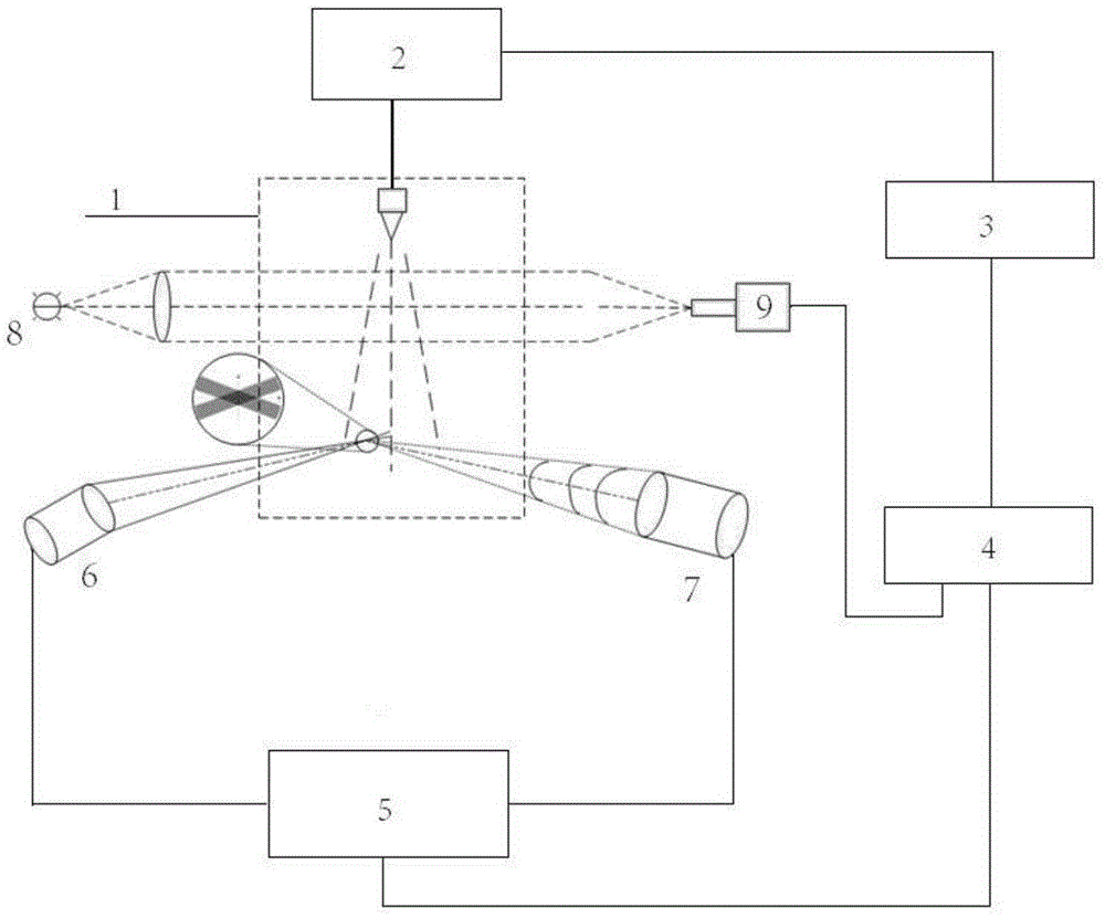
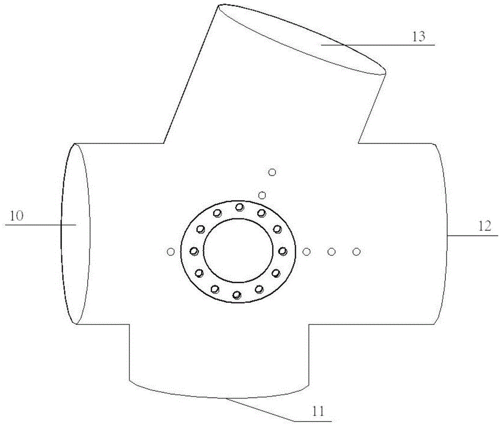
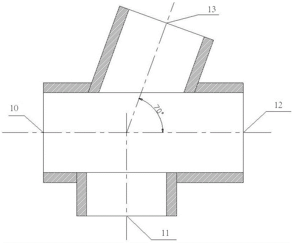
[0028] Such as figure 1 with figure 2 As shown, a system for synchronously measuring the macroscopic morphology and microscopic characteristics of the spray, including a constant volume combustion device 1, a fuel supply system 2 with a controller 3, a digital delay generator 4, and a phase Doppler particle analyzer 5 (PDA), LED lamp 8 and high-speed video camera 9, have transmitting probe 6 and receiving probe 7 on the phase Doppler particle analyzer 5 (PDA), constant volume combustion device 1 comprises the incendiary bomb body installed in the casing, Asbestos for heat preservation is filled between the box body and the incendiary bomb body, and the incendiary bomb body is provided with four observation holes in the shape of through holes, the axes of the observation holes are all on the same horizontal plane, and two of the observation holes The angle between the ax...


PUM


Abstract

The invention discloses a system and method for synchronously measuring spraying macromorphology and microscope properties. The system comprises a constant-volume combustion device, a fuel supply system, an LED (light emitting diode) lamp, a high-speed camera, a digital delay generator and a phase Doppler particle analyzer, wherein the fuel supply system is provided with a controller; the constant-volume combustion device consists of a box body and a combustion projectile body; the combustion projectile body is provided with four observation holes in the shape like a through hole; the axial lines of the observation holes are on the same horizontal plane; the angle between the axial lines of the two observation holes is 180 degrees; the included angle between the axial lines of the other two observation holes is 160 degrees; an optical observation window is arranged in each observation hole; the constant-volume combustion device is communicated with the fuel supply system; the controller is connected with the digital delay generator; the digital delay generator is connected with the phase Doppler particle analyzer and the high-speed camera. By the measuring method using the measuring system, the goal of synchronously measuring the spraying macromorphology and the microscope properties in the constant-volume combustion device is realized.

Description

technical field [0001] The invention relates to the field of constant-volume combustion devices, and more specifically, relates to a system and method for synchronously measuring the macroscopic appearance and microscopic characteristics of a spray. Background technique [0002] In the field of internal combustion engines, the atomization process of fuel directly affects the combustion and emission performance, thereby contributing to the alleviation of energy and environmental problems. Therefore, for internal combustion engine researchers, it is necessary to obtain fuel spray characteristics (jet breakage length, spray cone angle, oil droplet size and velocity, etc.) and its relationship with surrounding environmental parameters (pressure, temperature, ambient gas type and density, etc.) , and then establish the kinetic mechanism of fuel atomization reaction, and finally provide basic data for engine spray simulation and optimization, which is the main purpose of fuel inje...

Claims


Application Information

Patent Timeline
Patent Type & Authority Applications(China)
IPC IPC(8): G01N15/00G01N15/02
CPCG01N15/00G01N15/0205
Inventor 杨子明杜青白富强杨贤陈世兴
Owner TIANJIN UNIV
Learn More