Method and system for calibrating vehicle ultrasonic sensor

A calibration method and sensor technology, applied in the direction of radio wave measurement system, sound wave re-radiation, instruments, etc., can solve the problems of adverse effects of distance ability and achieve the effect of ensuring accuracy and consistency requirements

Active Publication Date: 2018-09-25
TUNG THIH ELECTRONICS (XIAMEN) CO LTD
View PDF8 Cites 0 Cited by
  • Summary
  • Abstract
  • Description
  • Claims
  • Application Information

AI Technical Summary

Problems solved by technology

[0003] The ability of an ultrasonic sensor to detect objects and report their distance can be adversely affected when the temperature of the outside air (i.e. the temperature of the outside air surrounding the vehicle) changes and / or the temperature of the sensor changes

Method used


Image

  • Method and system for calibrating vehicle ultrasonic sensor
  • Method and system for calibrating vehicle ultrasonic sensor

Examples


Embodiment 1

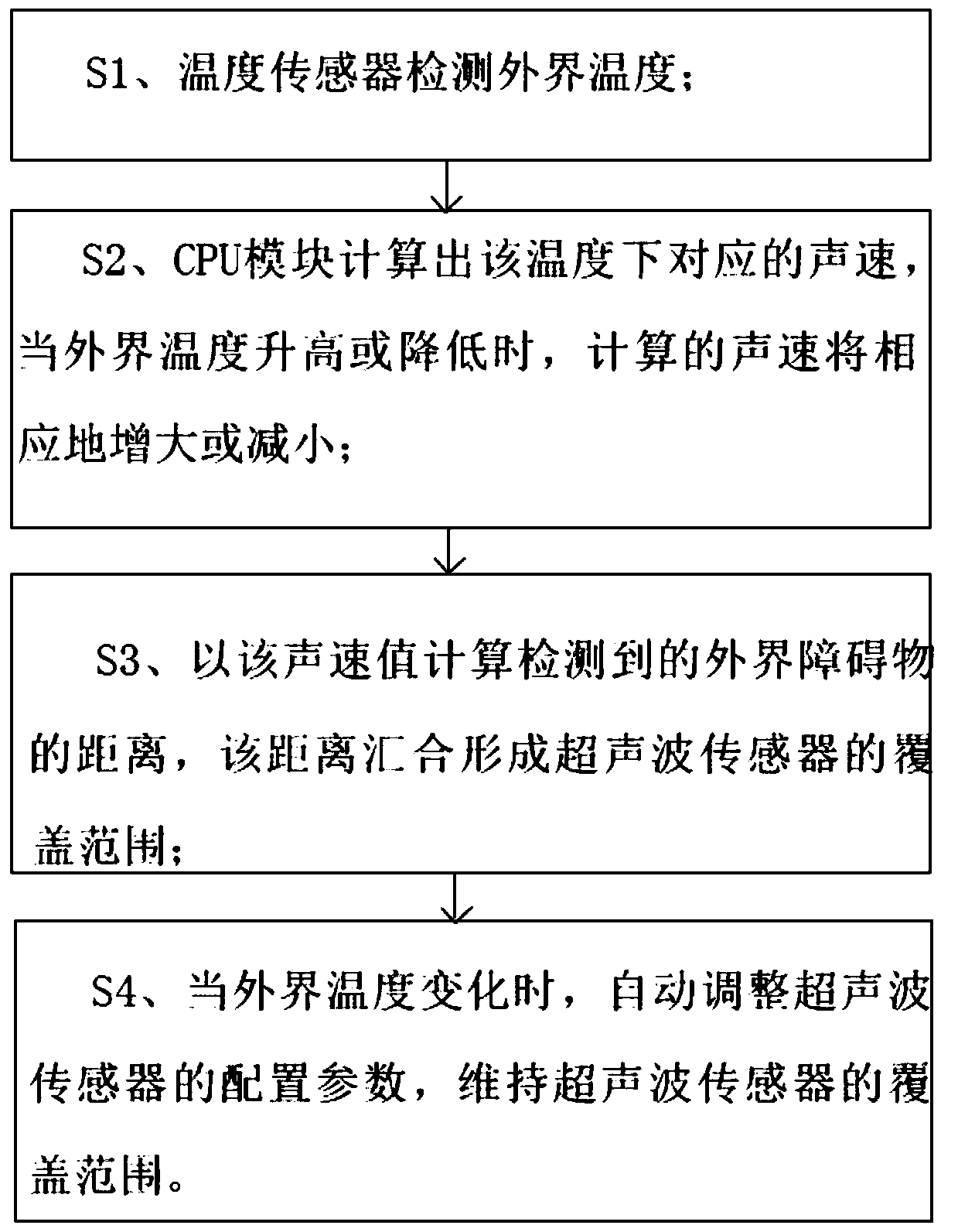
[0057] Embodiment 1: In the case where resources such as calculation speed and calculation space allow, directly use the theoretical formula Put the temperature into T in the formula to calculate the sound velocity at the current temperature. The speed of sound at the current temperature obtained by this method is close to the actual speed of sound.

Embodiment 2

[0058] Embodiment 2: In the case of limited resources including calculation speed and use of space, it is necessary to theoretically formulate Carry out simple processing within the range that can actually be used, thereby reducing the resources required for calculation; under normal circumstances, the actual outside temperature range can be taken from minus 40 degrees to minus 60 degrees, and this value can cover the area where the vehicle can normally drive . Take a value every 10 degrees for the temperature, respectively -40, -30...50, 60, calculate the sound speed corresponding to the temperature through the theoretical formula, and create a table in the reverse assist system or parking assist system. After the external temperature is obtained, the temperature range is determined by looking up the table, and the estimated value of the sound velocity corresponding to the current temperature is obtained through a linear formula. When the outside temperature is less than mi...

Embodiment 3

[0061] Embodiment 3: In the case of limited resources including calculation speed and use of space, it is necessary to analyze the theoretical formula Carry out simple processing within the range that can actually be used, thereby reducing the resources required for calculation; under normal circumstances, the actual outside temperature range can be taken from minus 40 degrees to minus 60 degrees, and this value can cover the area where the vehicle can normally drive . Take a value every 10 degrees for the temperature, respectively -40, -30...50,60, set the weight factor corresponding to each temperature, and adjust the weight factor to calculate the speed of sound and the temperature calculated by the theoretical formula The difference is reduced. When the outside temperature is greater than 60 degrees above zero, use the sound velocity temperature corresponding to 60 degrees above zero. Take the theoretical speed of sound at a temperature of minus 40 degrees as the refere...


PUM


Abstract

The present invention provides a vehicle ultrasonic sensor correction method and system. The system comprises a CPU module, a temperature sensor and at least one ultrasonic sensor. The vehicle ultrasonic sensor correction method and system employ a temperature sensor to detect external temperature, a CPU module is configured to calculate configuration parameters matching a desired detection precision and dynamically configure the ultrasonic sensor so as to make the detection coverage area of the ultrasonic sensor stay the same in different temperatures, the CPU module is configured to calculate the sound velocity at the temperature, and the sound velocity is used for calculating detected distance of an extraneous barrier so as to ensure the precision of barrier distance detection of the system. The vehicle ultrasonic sensor correction method and system only need few CPU sources to calculate required configuration parameters and sound velocity so as to ensure the precision requirement and the consistency requirement of a barrier distance detection of an ultrasonic sensor system and barrier shape detection when a vehicle is driving at different temperatures.

Description

technical field [0001] The invention relates to an ultrasonic sensor system that automatically adjusts configuration parameters according to changes in external temperature. By adjusting the parameters, the consistency of coverage of the ultrasonic sensor and the accuracy of obstacle distance calculation can be ensured. Background technique [0002] It is well known that ultrasonic sensors are used in many driver assistance applications to assist the driver of a vehicle. In such motor vehicle applications, ultrasonic sensors use sound waves through the air to determine the presence of objects and determine their distance. [0003] The ability of an ultrasonic sensor to detect objects and report their distance can be adversely affected when the temperature of the outside air (ie, the temperature of the outside air surrounding the vehicle) changes and / or the temperature of the sensor changes. To assist in mitigating such temperature-based variability in the performance of suc...

Claims


Application Information

Patent Timeline
Patent Type & Authority Patents(China)
IPC IPC(8): G01S7/52G01S15/93
Inventor 柯进益袁耀杭陈耀春
Owner TUNG THIH ELECTRONICS (XIAMEN) CO LTD
Why Eureka
Try Eureka