A touch display device and a touch detection method

A touch display device and touch signal technology, applied in static indicators, instruments, calculations, etc., can solve problems such as horizontal stripes in panel display images, and achieve the effect of increasing touch scanning frequency and touch reporting rate

Active Publication Date: 2021-01-05
SHANGHAI TIANMA MICRO ELECTRONICS CO LTD +1
View PDF5 Cites 0 Cited by
  • Summary
  • Abstract
  • Description
  • Claims
  • Application Information

AI Technical Summary

Problems solved by technology

However, in this method, when a touch phase is randomly inserted into the display phase of each frame, only the output signal of the gate drive circuit is turned off, and the input signal of the gate drive circuit still needs to be maintained. Therefore, when the touch phase is inserted, the Causes coupling with the input signal of the gate drive circuit, resulting in horizontal stripes in the panel display image

Method used


Image

  • A touch display device and a touch detection method
  • A touch display device and a touch detection method
  • A touch display device and a touch detection method

Examples


Embodiment Construction

[0019] The present invention will be further described in detail below in conjunction with the accompanying drawings and embodiments. It should be understood that the specific embodiments described here are only used to explain the present invention, but not to limit the present invention. In addition, it should be noted that, for the convenience of description, only some structures related to the present invention are shown in the drawings but not all structures.

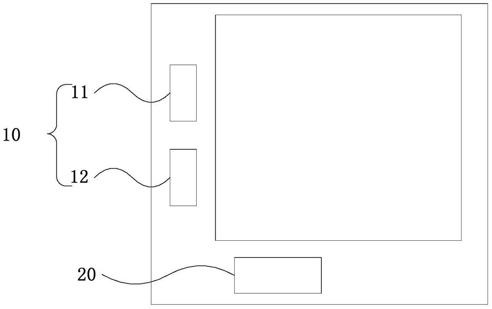
[0020] figure 2 A schematic structural diagram of a touch display device provided by an embodiment of the present invention, as shown in figure 2 As shown, the touch display device includes: a gate driving circuit 10 and a touch driving circuit 20 , wherein the gate driving circuit 10 includes a first circuit 11 and a second circuit 12 . During the driving cycle of one frame of picture, a display interruption period is set during the driving switching between the first circuit 11 and the second circuit 12 , and...


PUM


Abstract

The invention discloses a touch display device and a touch detection method. The touch display device comprises a grid drive circuit and a touch drive circuit; the grid drive circuit comprises a first circuit and a second circuit; in a one-frame picture drive period, a display interruption period is set in drive switch of the first circuit and the second circuit; and the touch drive circuit provides a touch signal in the display interruption period. The touch detection method comprises the following steps that: the grid drive circuit controls the first circuit and the second circuit in the one-frame picture drive period and provides a scanning signal for the touch display device; and the touch drive circuit provides the touch signal in the display interruption period.

Description

technical field [0001] The embodiments of the present invention relate to the technical field of touch display, and in particular, to a touch display device and a touch detection method. Background technique [0002] With the popularity of smart devices such as smartphones, touch display panels have also been widely used. Existing touch display devices generally require time-sharing driving of the touch display panel. Such as figure 1 As shown, the driving cycle of each frame includes a display phase A and a touch phase B. In the display phase A, the gate drive circuit of the touch display panel provides display scanning signals for the gate lines of the touch display panel for touch The touch display panel realizes the display function; in the touch stage B, the touch driving circuit of the touch display panel provides touch driving signals for the touch electrodes of the touch display panel, so that the touch display panel realizes the touch function. The above-mentione...

Claims


Application Information

Patent Timeline
Patent Type & Authority Patents(China)
IPC IPC(8): G06F3/041G09G3/20
CPCG06F3/0412G06F3/0416G06F3/0418G09G3/20
Inventor 王桂才周井雄
Owner SHANGHAI TIANMA MICRO ELECTRONICS CO LTD
Why Eureka
Try Eureka