
Cylindrical plug-in element

A connector and cylindrical technology, which is applied in the field of cylindrical connectors, can solve problems such as high requirements, wrong insertion by operators, instability, etc., and achieve the effects of improving service life, improving stability, and increasing binding force

Active Publication Date: 2016-06-01
苏州福羊自控科技有限公司
View PDF5 Cites 2 Cited by
  • Summary
  • Abstract
  • Description
  • Claims
  • Application Information

AI Technical Summary

Problems solved by technology

Because the male connector and the female connector are often plugged and pulled out, the connection is loose and unstable. If this happens for a long time, the connection between the plug on the male connector and the terminal on the female connector will be unstable, which will affect the normal operation of the circuit.
In addition, since the male connector of some connectors is often provided with multiple inserts, which correspond to multiple terminals on the female connector, the correct connection between the connector and the circuit board is unique. , when the insertion direction is correct, the circuit connection can only be realized by connecting with the corresponding terminal, which requires high requirements. However, the existing connector has no guide, and it is easy for the operator to insert it wrongly, resulting in damage to the circuit board.

Method used


Image

  • Cylindrical plug-in element
  • Cylindrical plug-in element
  • Cylindrical plug-in element

Examples


Embodiment Construction

[0030] The present invention will be further described in detail below in conjunction with the accompanying drawings, so that those skilled in the art can implement it with reference to the description.

[0031] It should be noted that the experimental methods described in the following embodiments, unless otherwise specified, are conventional methods, and the reagents and materials, if not otherwise specified, can be obtained from commercial sources; in the description of the present invention, The terms "landscape", "portrait", "top", "bottom", "front", "rear", "left", "right", "vertical", "horizontal", "top", "bottom", The orientation or positional relationship indicated by "inner", "outer", etc. is based on the orientation or positional relationship shown in the drawings, which is only for the convenience of describing the present invention and simplifying the description, and does not indicate or imply that the referred device or element must have Certain orientations, co...


PUM


Abstract

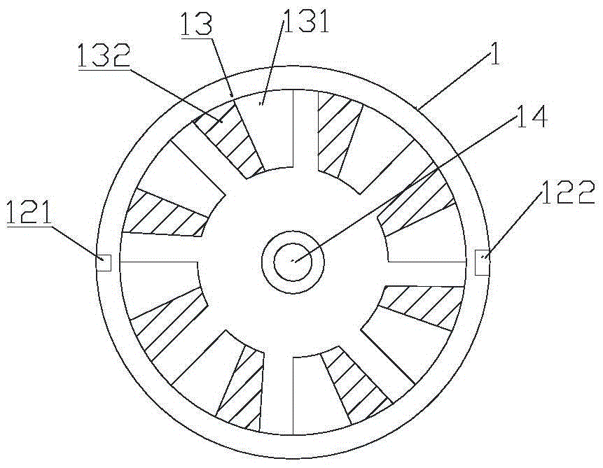
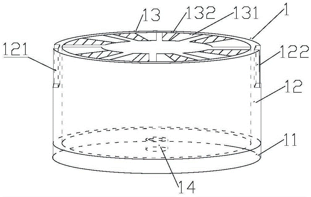
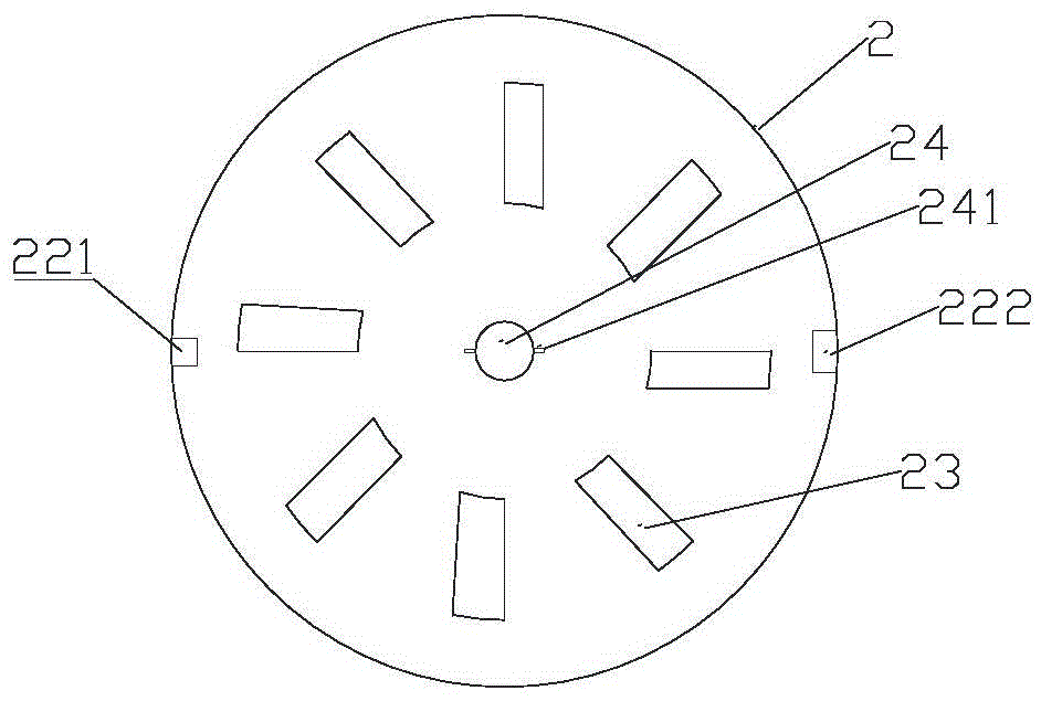
The invention discloses a cylindrical plug-in element. The cylindrical plug-in element comprises a female plug-in element, a male plug-in element and a locking rod, wherein the female plug-in element comprises a cylindrical first shell and at least three groups of electric conductors, wherein one end of each electric conductor is arranged in the first shell, a first blind groove and a second blind groove which have unequal cross sections are symmetrically arranged on the first shell, a jack is limited between arbitrary two groups of electric conductors, the male plug-in element comprises a cylindrical second shell and at least three insertion sheets, one end of each insertion sheet is arranged in the second shell, the inner diameter of the second shell is slightly larger than the external diameter of the first shell, a first bulge and a second bulge which are matched with the first blind groove and the second blind groove are arranged on the second shell, and the insertion sheets are matched with the jacks and are the same in quantity, so that the male plug-in element and the female plug-in element can be plugged with each other. The plug-in element disclosed by the invention has the advantages of shaking prevention, connection stability, long service lifetime and the like, directional plug can be achieved, and misplug is prevented.

Description

technical field [0001] The invention relates to the technical field of electrical connectors. More particularly, the present invention relates to a securely connected cylindrical connector. Background technique [0002] An electrical connector is a component used to connect two sections of power lines or data lines together for power or electronic data transmission. Its structure is that one section of the line is provided with a male connector, and the other section of the line connected to it is provided with a female connector. Insert the male connector into the female connector to connect the two lines. Because the male connector and the female connector are often plugged and pulled out, the connection is loose and unstable. If this happens for a long time, the connection between the plug on the male connector and the terminal on the female connector will be unstable, which will affect the normal operation of the circuit. In addition, since the male connector of some c...

Claims


Application Information

Patent Timeline
Patent Type & Authority Applications(China)
IPC IPC(8): H01R13/10H01R13/627H01R13/631
CPCH01R13/10H01R13/6273H01R13/6278H01R13/631
Inventor 谢飞平何为华刘雪芬
Owner 苏州福羊自控科技有限公司
Learn More