
Light field imaging system

A light field imaging and imaging technology, applied in the parts, optics and optical components of TV systems, etc., can solve the problems of discarding light propagation direction information and limiting image remodeling.

Active Publication Date: 2016-06-01
BEIJING ANTVR TECH
View PDF4 Cites 18 Cited by
  • Summary
  • Abstract
  • Description
  • Claims
  • Application Information

AI Technical Summary

Problems solved by technology

[0002] The imaging process of traditional cameras adopts a two-dimensional projection method for three-dimensional space scenes, and only accumulates the intensity of light on the detector pixels, that is to say, only the spatial distribution of objects on the image plane is considered, and the The propagation direction information of the light is discarded, and the reshaping of the image is limited

Method used


Image

  • Light field imaging system
  • Light field imaging system
  • Light field imaging system

Examples


Embodiment Construction

[0024] The objects and functions of the present invention and methods for achieving the objects and functions will be clarified by referring to the exemplary embodiments. However, the present invention is not limited to the exemplary embodiments disclosed below; it can be implemented in various forms. The essence of the description is only to help those skilled in the relevant art comprehensively understand the specific details of the present invention.

[0025] Hereinafter, embodiments of the present invention will be described with reference to the accompanying drawings. In the drawings, the same reference numerals represent the same or similar components, or the same or similar steps.

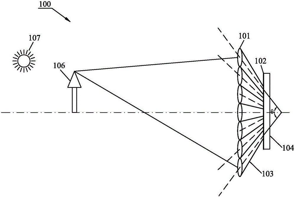
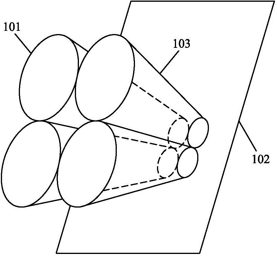
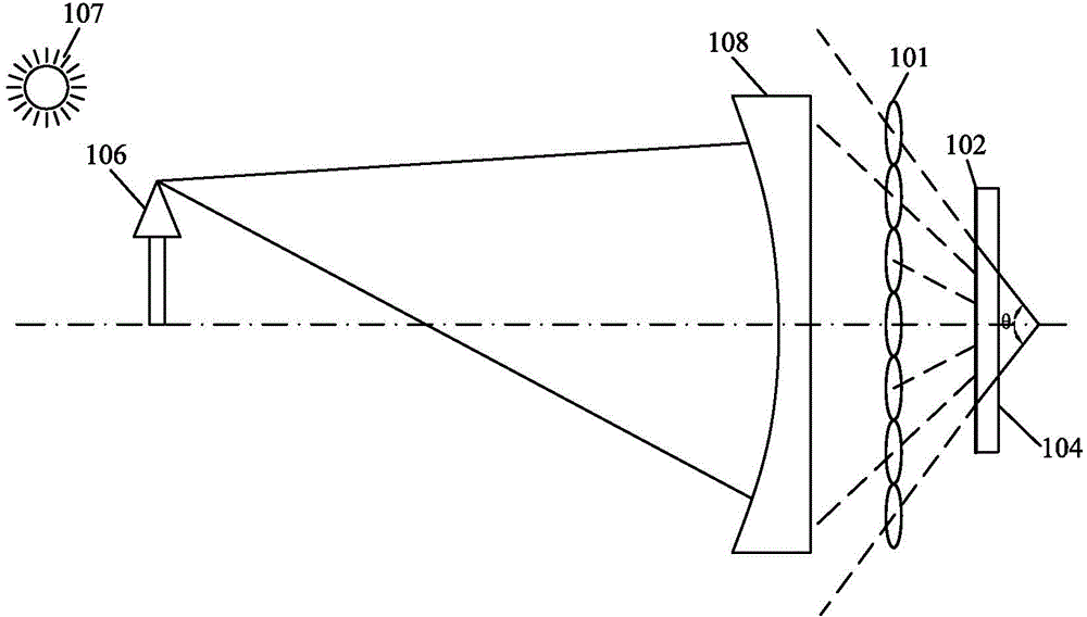
[0026] The light field imaging system according to the present invention includes a microlens array, a beam guiding unit, an imaging unit, and an image processing unit, wherein the microlens array includes a plurality of microlens units for focusing light beams; The light beam imaged by th...


PUM


Abstract

The invention provides a light field imaging system. The light field imaging system comprises a microlens array, a light beam guiding unit, an imaging unit and an image processing unit, wherein the microlens array comprises a plurality of microlens units used for focusing light beams; the light beam guiding unit is used for guiding the light beams imaged through the microlens array so as to enable light having a larger included angle with a light axis of the light field imaging system to be transmitted to the imaging unit through the microlens array; the imaging unit is arranged on a focal plane of the microlens array and is used for receiving light transmitted by the microlens array so as to carry out light sensitive imaging; and the image processing unit is used for processing electric signals collected by the imaging unit. According to the invention, the light field imaging system is simple in structure and is capable of collecting light with a larger view angle for light field imaging, so that the view field angel of the light field imaging system is effectively enlarged.

Description

technical field [0001] The invention relates to the technical field of light field imaging, in particular to a light field imaging system with a large viewing angle. Background technique [0002] The imaging process of traditional cameras adopts a two-dimensional projection method for three-dimensional space scenes, and only accumulates the intensity of light on the detector pixels, that is to say, only the spatial distribution of objects on the image plane is considered, and the The propagation direction information of the light is discarded, and the reshaping of the image is limited. [0003] In contrast, light field imaging technology retains the possibility of image reshaping, can obtain more flexible and diversified image information, and has a very broad application prospect. For example, the digital refocusing technology of light field pictures can be used to calculate the two-dimensional images focused at different depths, so as to realize the function of "taking pi...

Claims


Application Information

Patent Timeline
Patent Type & Authority Applications(China)
IPC IPC(8): H04N5/225G02B27/00
Inventor 覃政
Owner BEIJING ANTVR TECH
Learn More