
Camera module motor, camera module and electronic device

A technology for camera modules and electronic equipment, applied to televisions, electrical components, color TVs, etc., can solve the problems of multiple spaces for magnets 3, large camera module volume, and large camera module motor volume, and achieve simplified assembly process, Solve the effect of large volume and reduce the number of parts

Inactive Publication Date: 2016-06-01
TRULY OPTO ELECTRONICS
View PDF5 Cites 3 Cited by
  • Summary
  • Abstract
  • Description
  • Claims
  • Application Information

AI Technical Summary

Problems solved by technology

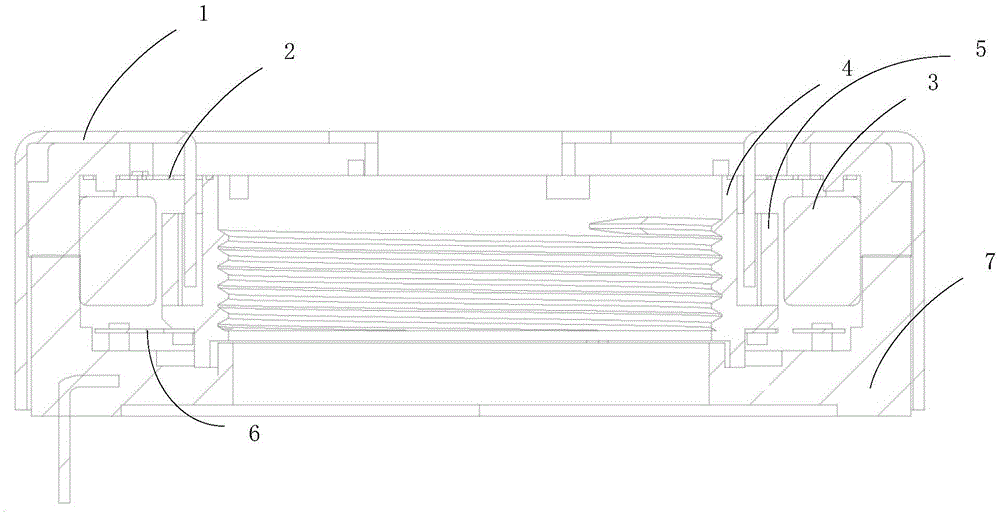
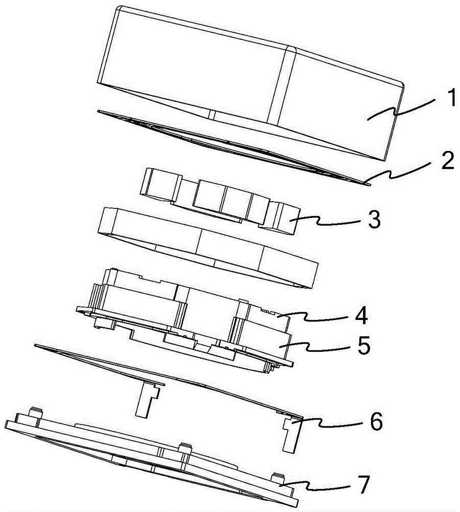
[0003] However, since one or more magnets 3 are needed to provide a magnetic field in actual use, and the magnets 3 will take up more space, the volume of the camera module motor is generally larger, which makes the application of the camera module motor The size of the camera module is relatively large

Method used


Image

  • Camera module motor, camera module and electronic device
  • Camera module motor, camera module and electronic device
  • Camera module motor, camera module and electronic device

Examples


Embodiment Construction

[0021] As mentioned in the background art, the camera module motor in the prior art needs a magnet to provide a magnetic field, which leads to a large volume of the camera module motor, and thus makes the camera module using the camera module motor Larger volume.

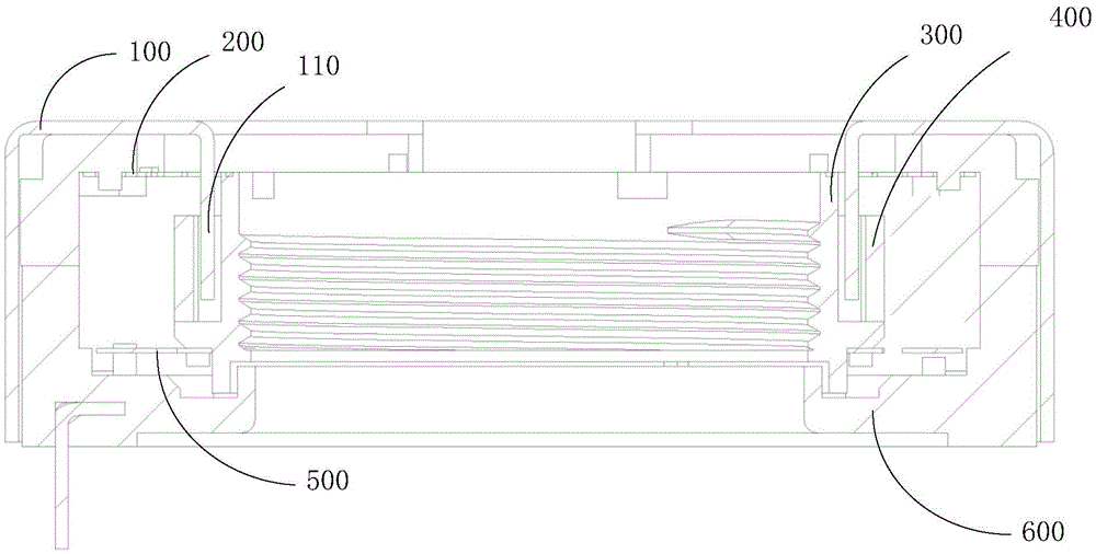
[0022] In view of this, the embodiment of the present application provides a camera module motor, which includes a housing, an upper elastic piece, a lens carrier, a coil, a lower elastic piece and a base, and the housing and the base form a hollow receiving cavity after fitting , the upper elastic piece, the lens carrier, the coil and the lower elastic piece are located in the storage cavity, and the lens carrier accommodates a lens;

[0023] Wherein, the yoke of the housing is magnetic.

[0024] Correspondingly, the embodiment of the present application also provides a camera module, including at least one lens and camera module motors corresponding to the number of lenses, and the camera module motor is the came...


PUM


Abstract

The present invention discloses a camera module motor, a camera module and an electronic device. The camera module motor comprises a housing, an upper spring, a lens carrier, a coil, a lower spring and a pedestal; the housing and the pedestal are embedded to from a hollow holding cavity, the upper spring, the lens carrier, the coil and the lower spring are located in the holding cavity, and a lens is held in the lens carrier, wherein the magnet yoke of the housing has magnetic property. Because the magnet yoke of the housing has magnetic property, the magnet yoke is able to provide a required magnetic field for the coil; when the coil is flowed by current in a certain size, the lens carrier winding the coil may carry the lens to move in the magnetic field provided by the magnet yoke to realize the focusing function of the camera module; and therefore, the camera module motor, camera module and electronic device are able to solve the problem that the size of the camera module motor is large caused by the large space occupied by the magnet, reduce the numbers of parts of the camera module motor and simplify the assembly process of the camera module motor with no need for an individually arranged magnet.

Description

technical field [0001] The present application relates to the technical field of imaging equipment, and more specifically, to a camera module motor, camera module and electronic equipment. Background technique [0002] The camera module motor is an essential device for the camera module to realize the focusing function. The structure reference of the camera module motor figure 1 and figure 2 , figure 1 It is a schematic cross-sectional structure diagram of a camera module motor in the prior art, figure 2 for figure 1 The schematic diagram of the split structure of the camera module motor shown, the camera module motor includes a housing 1, an upper elastic piece 2, a magnet 3, a lens carrier 4, a coil 5, a lower elastic piece 6 and a base 7, wherein the coil 5 is wound on The outside of the lens carrier 4 containing the lens. Since the energized conductor will move in the magnetic field, when a certain amount of current is passed into the coil 5, the lens carrier 4 wr...

Claims


Application Information

Patent Timeline
IPC IPC(8): H04N5/225
CPCH04N23/51H04N23/57H04N23/55H04N23/54
Inventor 王军伟王利霞
Owner TRULY OPTO ELECTRONICS
Learn More