A water-cooled heat dissipation structure for a drive motor and a motor controller

A motor controller and water cooling technology, which is applied in the field of automobile manufacturing, can solve the problem of uneven heat dissipation of a single-channel cooling water circuit, and achieve the effects of preventing heat redundancy, avoiding heat concentration, and balancing the flow rate.

Active Publication Date: 2018-01-09
奇瑞新能源汽车股份有限公司
View PDF4 Cites 0 Cited by
  • Summary
  • Abstract
  • Description
  • Claims
  • Application Information

AI Technical Summary

Problems solved by technology

[0006] In order to overcome the above technical problems, the object of the present invention is to provide a new multi-channel water-cooling heat dissipation structure, which can solve the problem of uneven heat dissipation of the existing single-channel cooling water channel, and will not increase the cost

Method used


Image

  • A water-cooled heat dissipation structure for a drive motor and a motor controller
  • A water-cooled heat dissipation structure for a drive motor and a motor controller
  • A water-cooled heat dissipation structure for a drive motor and a motor controller

Examples


Embodiment Construction

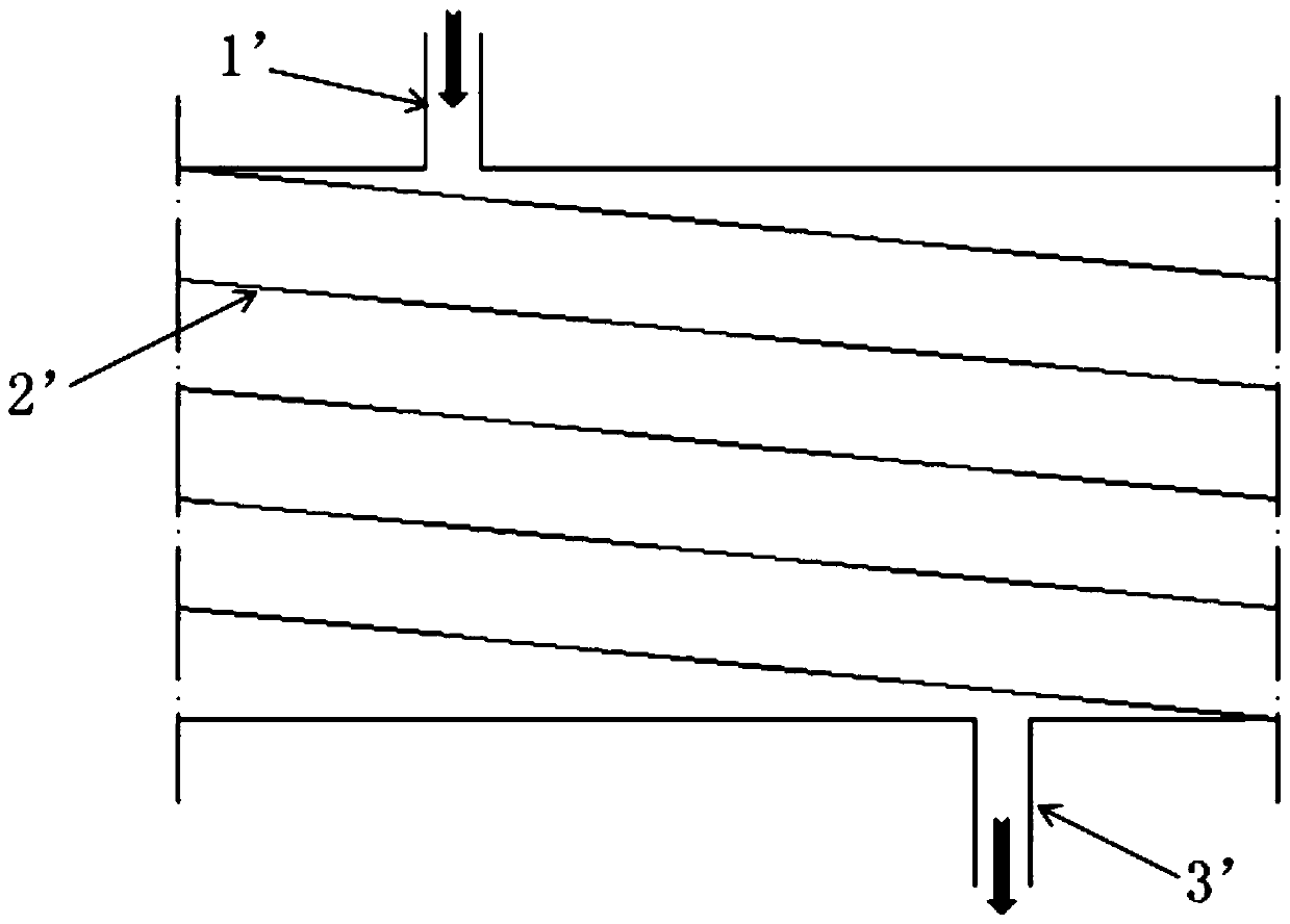
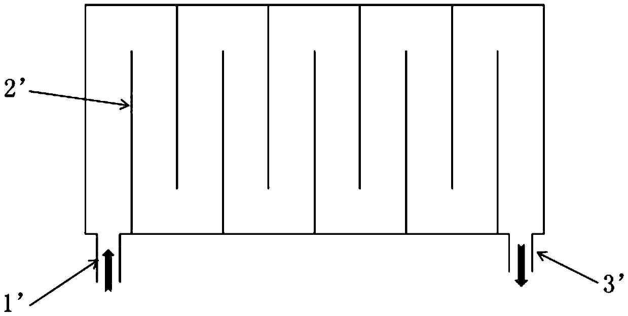
[0017] Please also refer to Figures 1 to 2 , the figure shows two existing single-channel water-cooling heat dissipation structures, that is, spiral and S-shaped, both of which can form a continuous cooling medium channel, but both have the problem of heat concentration at the end of the flow channel.

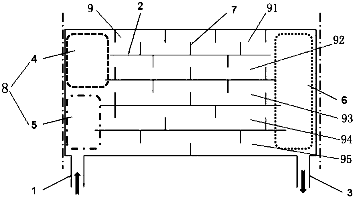
[0018] Examples, see image 3 , a water-cooled heat dissipation structure for driving a motor and a motor controller, comprising a cooling medium inlet 1 and a cooling medium outlet 3, a high-pressure area 8 arranged on the side of the cooling medium inlet 1, and a low-pressure area arranged on the side of the cooling medium outlet 3 6, and five cooling channels 9 arranged between the high pressure area 8 and the low pressure area 6.

[0019] Among them, the high-pressure area 8 is composed of a sub-high pressure area 5 and a high-pressure area 4, the cooling medium inlet 1, the sub-high pressure area 5 and the high-pressure area 4 are arranged linearly in sequence along the ...


PUM


Abstract

The invention discloses a water-cooling and heat dissipation structure for a drive motor and a motor controller, comprising a cooling medium inlet and a cooling medium outlet, a high-pressure area arranged on the side of the cooling medium inlet, a low-pressure area arranged on the side of the cooling medium outlet, and At least two cooling channels are disposed between the high pressure region and the low pressure region. Wherein, the high-pressure area is composed of a sub-high pressure area and a high-pressure area, and the above-mentioned cooling medium inlet, sub-high pressure area and high-pressure area are linearly arranged sequentially along the flow direction of the cooling medium. Each cooling flow channel is separated from each other by a partition plate, and a group of flow guide ribs for increasing flow channel resistance are respectively arranged in each cooling flow channel. The present invention adopts the method of increasing flow channel resistance, and designs the flow resistance of each multi-channel flow channel, so that the cooling medium flows through each flow channel evenly to avoid heat concentration at the tail of the existing single-channel flow channel, and is similar to the traditional heat dissipation structure. than, no additional cost will be added.

Description

technical field [0001] The invention relates to the field of automobile manufacturing, in particular to occasions with high heat dissipation requirements and high temperature control precision, and can be used in motor controllers of pure electric vehicles and drive motors of hybrid electric vehicles. Background technique [0002] With the development of hybrid electric vehicles and pure electric vehicles, the drive motors and motor controllers are limited by the space they are arranged in the front cabin of the vehicle, and are developing in the direction of smaller and larger power. Especially in hybrid vehicles, the drive motor is often arranged between the engine and the gearbox, and is affected by the heat radiation when the engine is working, and the working environment is very harsh, which puts forward higher requirements for its heat dissipation design. For pure electric vehicles, the working environment of motor controllers is also the same. [0003] For the drive ...

Claims


Application Information

Patent Timeline
Patent Type & Authority Patents(China)
IPC IPC(8): H05K7/20
Inventor 李陈勇裴善忠张杰
Owner 奇瑞新能源汽车股份有限公司
Why Eureka
Try Eureka