An attitude-changing valve assembly robot gripper and its working process

A technology of working process and robot hand, which is applied in the field of intelligent robots, can solve the problems of high cost, complicated process, and low efficiency, and achieve the effect of improving assembly efficiency, improving assembly accuracy, and reducing costs

Active Publication Date: 2017-12-19
SHANGHAI FANUC ROBOTICS
View PDF7 Cites 0 Cited by
  • Summary
  • Abstract
  • Description
  • Claims
  • Application Information

AI Technical Summary

Problems solved by technology

Due to the high precision and complicated process of valve assembly, manual assembly is mostly used for valve assembly nowadays, which has low efficiency and high cost.
However, in actual production, the automation level of assembly operations is far lower than that of other operations, which has become the main constraint factor for improving productivity.

Method used


Image

  • An attitude-changing valve assembly robot gripper and its working process
  • An attitude-changing valve assembly robot gripper and its working process
  • An attitude-changing valve assembly robot gripper and its working process

Examples


Embodiment 1

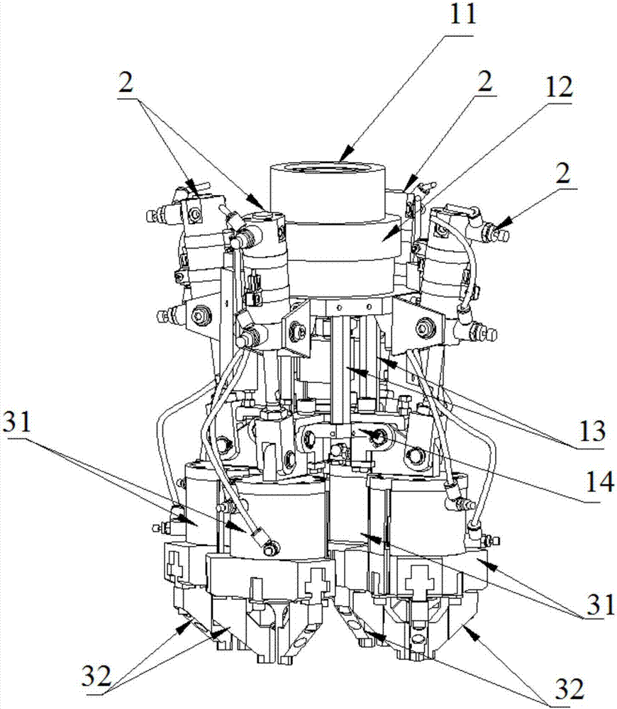
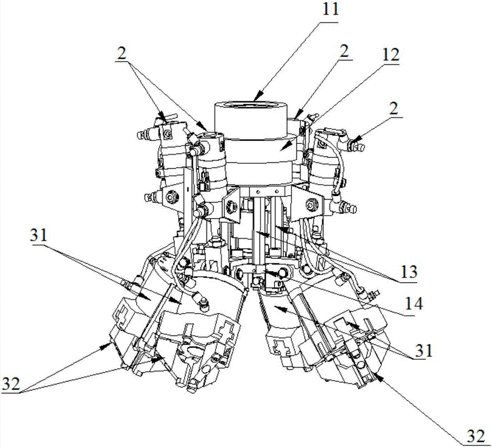
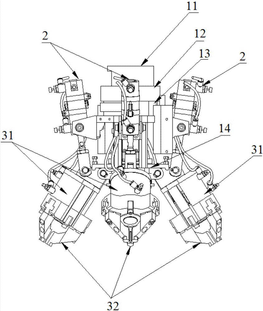
[0058] Such as figure 1 As shown, a valve assembly robot gripper that can change the attitude, including:

[0059] A fixing device, the fixing device is provided with a robot flange 11 for connecting the gripper with the robot;

[0060] Several guide rod cylinders 2 are fixedly arranged on the fixing device;

[0061] A plurality of single-hand claws are fixedly arranged on the fixing device, and are connected with the guide rod cylinder 2 in one-to-one correspondence, for grabbing the valve stem 01 .

[0062] Wherein, the single-hand claw can be a three-claw cylinder 31, which is connected to the guide rod cylinder 2 in one-to-one correspondence, and the different three-claw cylinders 31 are hinged to each other; in addition, the three-claw cylinder 31 is connected to the The fixture securely connects.

[0063] The three-claw cylinder 31 is provided with three claws 32, and the three-claw cylinder 31 is fixedly provided with the three claws 32 for grabbing the valve stem 01...

Embodiment 2

[0081] According to the posture-changing valve assembly robot gripper provided by the above-mentioned embodiments, this embodiment provides the working process of the valve assembly robot gripper capable of changing postures.

[0082] Such as Figure 7A As shown, the working process of a valve assembly robot gripper that can change the attitude includes the steps:

[0083] S1: All guide rod cylinders 2 shrink, and all single-hand claws open;

[0084] S2: Use the visual camera 4 to position the valve stem 01 to obtain the positioning information of the valve stem 01;

[0085] S3: The robot adjusts the position of the gripper according to the positioning information of the valve stem 01;

[0086] S4: All the guide rod cylinders 2 are stretched out, driving all the single-handed claws to gather together, so that the grasping directions of all the single-handed claws are consistent;

[0087] S5: Each of the single-hand claws grabs a valve stem 01 from the tray;

[0088] S6: us...


PUM


Abstract

The invention provides a valve assembly robot gripper with the posture capable of being changed and a working process of the valve assembly robot gripper. The gripper comprises a fixing device, multiple guide rod air cylinders and multiple single gripper bodies. A robot flange is arranged at the top of the fixing device, and the fixing device is used for connecting the gripper with a robot. The multiple guide rod air cylinders are fixedly arranged on the fixing device. The multiple single gripper bodies are evenly and fixedly arranged on the periphery of the fixing device and are connected with the guide rod air cylinders in a one-to-one correspondence manner. The single gripper bodies are hinged to one another. A visual camera is arranged in the center of the bottom of the fixing device and used for positioning assembly holes and / or valve rods in a material disc. By means of the valve assembly robot gripper with the posture capable of being changed, due to the cooperative use of the visual camera and a pressure sensor, the assembling precision is improved, the problem that automatic assembly is hard to achieve is solved, the assembly efficiency is further improved, and cost is reduced.

Description

technical field [0001] The invention relates to the field of intelligent robots, in particular to a valve assembly robot claw capable of changing attitude and its working process. Background technique [0002] In the automotive industry, the performance of the engine directly affects the performance of the car, and the valve is the gate valve for the intake and exhaust of the engine, which directly affects the power, economy, reliability and durability of the engine. Due to the high requirements for valve assembly accuracy and complicated process, nowadays valve assembly is mostly manual assembly, which has low efficiency and high cost. However, in actual production, the automation level of assembly operations is far lower than that of other operations, which has become the main constraint factor for improving productivity. Therefore, it is an urgent problem to provide an automatic valve assembly robot to improve the production efficiency of valves. Contents of the invent...

Claims


Application Information

Patent Timeline
Patent Type & Authority Patents(China)
IPC IPC(8): B25J15/10B25J19/02B25J19/04
CPCB25J15/10B25J19/02B25J19/04
Inventor 李生龙方克昊单齐勇陈竟新董德权刘明
Owner SHANGHAI FANUC ROBOTICS
Why Eureka
Try Eureka