Rapid separation equipment for catalytic cracking riser outlet
A catalytic cracking and riser technology, applied in the fields of fluidized catalytic cracking and petrochemical industry, can solve the problems of large system occupied space, low separation efficiency of oil and gas and catalyst, coking and other problems
- Summary
- Abstract
- Description
- Claims
- Application Information
AI Technical Summary
Problems solved by technology
Method used
Image
Examples
Embodiment 1
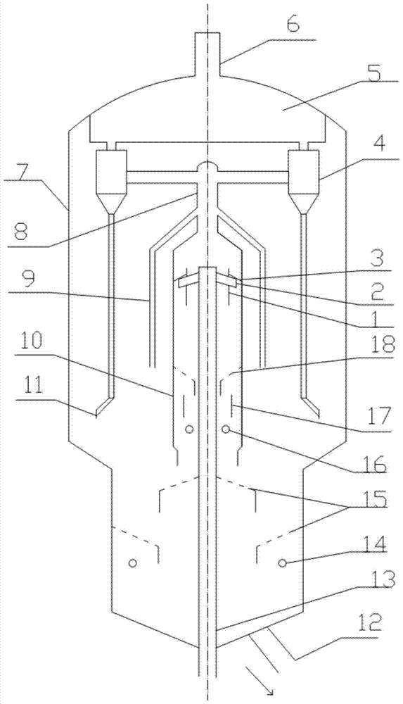
[0055] Such as figure 1 As shown, the oil gas and catalyst particles at the outlet of the riser 13 are sprayed out by the swirl arm with the splitter tube 1 and the splitter baffle 3 swirl quick splitter 2, and then rotate rapidly in the closed cover 10 to quickly separate the two phases of the oil agent , the separated catalyst particles rotate and flow downward along the side wall of the closed cover, and enter the inner ring between the circulating tube 17 of the dense-phase circulating pre-stripping device and the outer wall of the riser through the conical blanking stripping baffle 18, and the inner ring Under the action of the stripping steam air pipe 16, the density difference between the inner and outer rings of the circulation cylinder realizes the dense-phase circulation pre-stripping of the catalyst particles, and the catalyst particles after the pre-stripping enter the lower stripping section and pass through the disc ring baffle. 15 and under the effect of strippi...
Embodiment 2
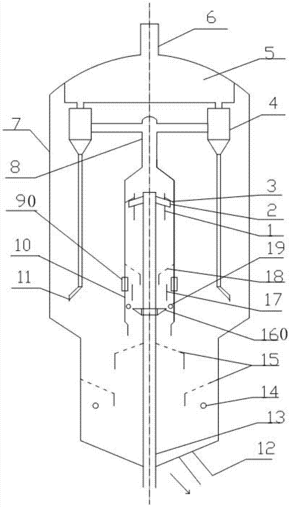
[0057] Such as figure 2 As shown, the implementation process of the second embodiment is similar to that of the first embodiment. There are two main differences between embodiment two and embodiment one. One is that embodiment two adopts a plurality of slots 90 arranged on the closure cover 10 to replace the balance tube 9 provided in the settler in embodiment one, and the number of slots 90 The axial position is between the conical blanking stripping baffle 18 and the circulation cylinder 17, so that the structure is simpler, the space is more compact, and it is more conducive to reducing coking in the settler. The oil gas and stripping steam from the stripping section enter the closed cover through the slot, and then enter the draft tube after passing through the conical stripping baffle plate and the splitter tube. The second is that embodiment two sets the outer ring stripping steam air duct at the outer ring of the circulating pre-stripping device, and replaces the inne...
Embodiment 3
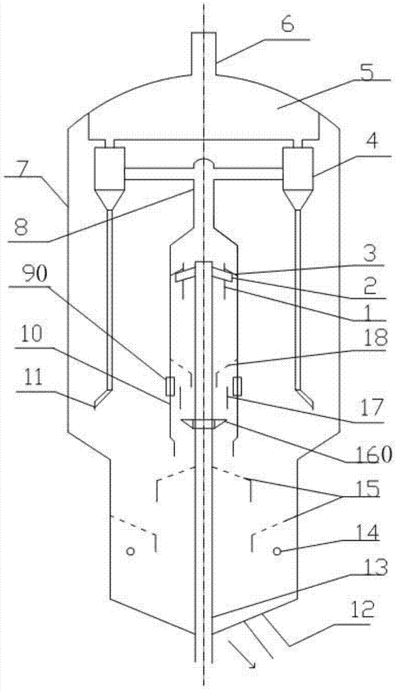
[0059] Such as image 3 As shown, the implementation technological process of embodiment three is similar to embodiment two, and the two are different: embodiment three is not in the enclosure, and the outer ring of the circulation pre-stripping device is provided with the outer ring stripping steam air duct 19 , the structure is relatively simple. In order to achieve relatively smooth dense-phase circulating flow, the inventor has obtained the inner ring cross-sectional area and the outer ring cross-sectional area (the inner ring cross-sectional area between the circulating tube and the outer wall of the riser) of the dense-phase circulating pre-stripper through long-term experiments and calculations. The ratio of the area to the cross-sectional area of the outer ring between the circulating cylinder and the closed cover) is between 0.3 and 0.4 (this can make the catalyst form a smooth dense-phase circulating flow and improve the operating flexibility of the dense-phase cir...
PUM
| Property | Measurement | Unit |
|---|---|---|
| pore size | aaaaa | aaaaa |
| porosity | aaaaa | aaaaa |
Abstract
Description
Claims
Application Information
 - R&D
- Intellectual Property
- Life Sciences
- Materials
- Tech Scout
- Unparalleled Data Quality
- Higher Quality Content
- 60% Fewer Hallucinations
Browse by: Latest US Patents, China's latest patents, Technical Efficacy Thesaurus, Application Domain, Technology Topic, Popular Technical Reports.
© 2025 PatSnap. All rights reserved.Legal|Privacy policy|Modern Slavery Act Transparency Statement|Sitemap|About US| Contact US: help@patsnap.com


