Energy-saving cloth dyeing machine

A technology for dyeing machines and fabrics, applied in the direction of processing textile material equipment configuration, spraying/jetting textile material processing, etc., can solve the problems of large amount of water resources, high processing cost, uneven color, etc., to eliminate uneven dyeing and simple operation. , the effect of improving efficiency

Active Publication Date: 2016-06-08
吴江市奕萱纺织有限公司
View PDF4 Cites 5 Cited by
  • Summary
  • Abstract
  • Description
  • Claims
  • Application Information

AI Technical Summary

Problems solved by technology

[0003] At present, the main working principle of exhaust dyeing is to set the dye liquor tank in the dyeing machine, use the circulation pump to promote the circulation of the dye liquor, raise the dye liquor to a certain temperature through the heat exchanger assembly, and then flow through the filter assembly to filter, flow to the nozzle, and the nozzle The dyeing solution is sprayed onto the fabric driven by pressure, and the fabric continues to move into the dyeing solution tank for dip-dyeing after spraying, and the fabric circulates in the main cylinder of the dyeing machine under the lifting of the lifting assembly of the lifting roller and the pressing roller , but under the action of gravity in the dyeing solution, the cloth is easy to stack in the dye tank, resulting in uneven dyeing
At the same time, although the pressing roller can keep the fabric flat, the pressing roller will also squeeze the fabric at the same time, which will cause the colored fabric to be squeezed to an uneven color during the circulation process to a certain extent.
[0004] This kind of dyeing machine needs to put a lot of dyeing liquid in the dye tank, but the coloring rate is not high. It not only needs a lot of water resources, but also produces a lot of sewage. Sewage treatment not only requires professional sewage treatment equipment to achieve Emission standards and high processing costs

Method used


Image

  • Energy-saving cloth dyeing machine
  • Energy-saving cloth dyeing machine

Examples


Embodiment Construction

[0022] In order to further understand the present invention, preferred embodiments of the present invention are described below in conjunction with examples, but it should be understood that these descriptions are only to further illustrate the features and advantages of the present invention, rather than limit the claims of the present invention.

[0023] The solutions in the embodiments of the present invention are clearly and completely described below in conjunction with the drawings in the embodiments of the present invention.

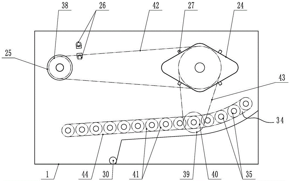
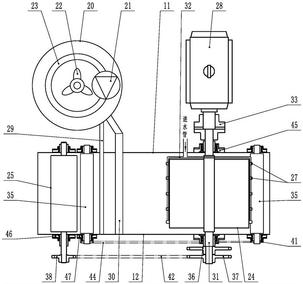
[0024] An energy-saving fabric dyeing machine according to an embodiment of the present invention includes a box body 1, a water tank 20, a transmission device 28, a conveying material row pipe 34, and a dye injection probe. The box body 1 includes an upper frame 11 and a lower frame 12; A driving shaft 31, a cloth lifting roller 24, and a guide roller 25 are arranged in the body 1, and a high-pressure pump 21, a turbine agitator 22, and a steam el...


PUM


Abstract

The invention discloses an energy-saving cloth dyeing machine which comprises a box, a water bucket and a transmission device. A drive rotating shaft, a cloth lifting roll, a guide roll, a cloth conveying calandria and dye injection probes are arranged in the box; the cloth lifting roll is provided with water spray probes connected with a water inlet pipe; the dye injection probes are close to the guide roll and connect a dye discharge pipe to the water bucket; the cloth conveying calandria is formed by combining a plurality of drums. According to the energy-saving cloth dyeing machine, the structure is simple, use is convenient; the two faces of cloth are simultaneously spray-dyed by the dye spray probes, a dye tank is not arranged, and dip dyeing does not needed to be performed; the two faces of the dyed cloth are rinsed by the water spray probes, water is saved, and sewage is not generated; the cloth smoothly and slowly moves in the dyeing machine through the cloth lifting roll, the guide roll and the cloth conveying calandria, the cloth can be prevented from being stacked, and uniform dyeing can be achieved.

Description

technical field [0001] The invention relates to the technical field of textile dyeing equipment, in particular to an energy-saving cloth dyeing machine. Background technique [0002] There are generally two types of fabric dyeing processing techniques, painting and exhaust dyeing. Due to problems such as poor washing fastness, uneven light fastness, and uneven dyeing of painted fabrics, the industry generally uses exhaust dyeing to dye fabrics. [0003] At present, the main working principle of exhaust dyeing is to set the dye liquor tank in the dyeing machine, use the circulation pump to promote the circulation of the dye liquor, raise the dye liquor to a certain temperature through the heat exchanger assembly, and then flow through the filter assembly to filter, flow to the nozzle, and the nozzle The dyeing solution is sprayed onto the fabric driven by pressure, and the fabric continues to move into the dyeing solution tank for dip-dyeing after spraying, and the fabric cir...

Claims


Application Information

Patent Timeline
Patent Type & Authority Applications(China)
IPC IPC(8): D06B1/02D06B23/20
CPCD06B1/02D06B23/20
Inventor 邵建寿姚凯
Owner 吴江市奕萱纺织有限公司
Why Eureka
Try Eureka