Coloring device for textile raw material

A raw material and textile technology, applied in the field of textile raw material coloring devices, can solve problems such as a large amount of sewage, uneven coloring, poor washing fastness, etc., and achieve the effects of improving efficiency, uniform coloring, and saving dyes

Inactive Publication Date: 2018-06-08
SUZHOU BUDE MECHANICAL & ELECTRICAL EQUIP CO LTD
View PDF0 Cites 3 Cited by
  • Summary
  • Abstract
  • Description
  • Claims
  • Application Information

AI Technical Summary

Problems solved by technology

[0002] Textile raw materials are generally divided into two types of coloring methods, dyeing and dip-dyeing. Due to the poor washing fastness and uneven dyeing of the dyed fabrics, most of the industry uses dip-dyeing to color textile raw materials.
[0003] There are certain disadvantages in the existing dyeing technology for fabrics. Most of the time, the fabrics are placed in the dye vat for dip-dyeing. Due to the effect of gravity and water pressure, the fabrics are easy to stack in the dye vat. It leads to uneven coloring and low coloring rate. In this case, a large amount of dyeing solution is required, which not only requires a large amount of water resources, but also produces a large amount of sewage. The cost of sewage treatment is relatively high, and professional sewage treatment equipment is required. To meet the emission standards, it has brought a certain impact. For this reason, we propose a textile raw material coloring device

Method used


Image

  • Coloring device for textile raw material
  • Coloring device for textile raw material

Examples


Embodiment Construction

[0015] In order to make the technical means, creative features, goals and effects achieved by the present invention easy to understand, the present invention will be further described below in conjunction with specific embodiments.

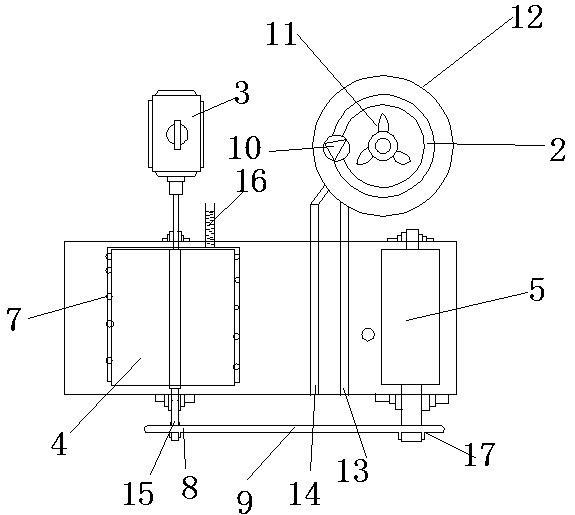
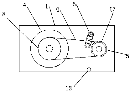
[0016] Such as Figure 1-2 As shown, a textile raw material coloring device includes a box body 1, a bucket 2, a transmission device 3 and a water inlet pipe 16. The inside of the box body 1 is provided with a driving wheel 4, and one side of the driving wheel 4 is provided with a The driving wheel 5, the upper end of the driving wheel 4 is provided with a water spray probe 7, the water inlet pipe 16 is movably connected with the water spray probe 7, the box 1 is provided with a dye spray probe 6, and the bottom of the transmission device 3 Be provided with transmission shaft 15, the outside of transmission shaft 15 is provided with driving wheel 4, and transmission device 3 is fixedly connected with driving wheel 4 by transmission shaft 15, and o...


PUM


Abstract

The invention discloses a coloring device for a textile raw material. The device comprises a box body, a water bucket, a transmission device and a water inlet pipe, wherein a driving wheel and a driven wheel are arranged in the box body; a water spray probe is arranged at the upper end of the driving wheel; an injection dye probe is arranged in the box body; a transmission shaft is arranged in thebottom of the transmission device; the driving wheel is arranged on the outer side of the transmission shaft; a driving chain wheel is arranged on one side of the transmission shaft; a return pipe isarranged in the bottom of the box body, and a dye outlet pipe is arranged on one side of the return pipe; and a worm wheel stirrer, a worm high pressure pump and a steam electric heating tube are arranged in the water bucket. The coloring device for the textile raw material is provided with the injection dye probe and the return pipe to spray dye to two sides of textile cloth without a dip dyeingprocess. The dye sprinkled to the bottom of the box body can flow to a wooden barrel to be repeatedly used, so that coloring without discharge and water-saving effect are achieved. The coloring device is suitable for different working conditions, and brings a better application prospect.

Description

【Technical field】 [0001] The invention relates to the technical field of textile dyeing equipment, in particular to a textile raw material coloring device. 【Background technique】 [0002] Textile raw materials are generally divided into two types of coloring methods, painting and dip-dyeing. Due to the poor washing fastness and uneven dyeing of painted fabrics, most of the industry uses dip-dyeing to color textile raw materials. [0003] There are certain disadvantages in the existing dyeing technology for fabrics. Most of the time, the fabrics are placed in the dye vat for dip-dyeing. Due to the effect of gravity and water pressure, the fabrics are easy to stack in the dye vat. It leads to uneven coloring and low coloring rate. In this case, a large amount of dyeing solution is required, which not only requires a large amount of water resources, but also produces a large amount of sewage. The cost of sewage treatment is relatively high, and professional sewage treatment equ...

Claims


Application Information

Patent Timeline
Patent Type & Authority Applications(China)
IPC IPC(8): D06B1/02D06B23/20D06B23/22
CPCD06B1/02D06B23/20D06B23/205D06B23/22
Inventor 郝敬丽
Owner SUZHOU BUDE MECHANICAL & ELECTRICAL EQUIP CO LTD
Why Eureka
Try Eureka