An injection-molded support bolt device and its construction method

An anchor rod and injection molding technology, which is applied in the direction of anchor rod installation, earthwork drilling, infrastructure engineering, etc., can solve the problems of restricting rapid support, low efficiency, and cumbersome anchor rod support technology, and achieves universality and practicability. , Improve the support effect and simplify the effect of the support process

Inactive Publication Date: 2017-02-15
黄胜
View PDF7 Cites 0 Cited by
  • Summary
  • Abstract
  • Description
  • Claims
  • Application Information

AI Technical Summary

Problems solved by technology

At present, the support bolts are all of a single structure, the bolt support process is cumbersome, the efficiency is low, and the full-length anchoring cannot be realized, and the support of the extended bolt cannot be realized due to space constraints, which restricts the realization of comprehensive mechanized rapid support. The reform of bolt support technology

Method used


Image

  • An injection-molded support bolt device and its construction method
  • An injection-molded support bolt device and its construction method
  • An injection-molded support bolt device and its construction method

Examples


Embodiment 1

[0038] A kind of support bolt construction method, comprises the following steps:

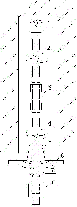
[0039] a. Tightly connect the inner threaded end of the anchor drill bit with the outer threaded end of the front end anchor rod, the anode end of the front end anchor rod body is connected to the cathode end of the injection-molded hybrid connector, start the anchor drill rig to connect the anchor drill bit and the front end anchor The rod body is slowly pushed into the anchor end face, and at the same time, water is injected into the through hole of the anchor rod from the water supply pipeline, part of the water is injected into the drill hole through the through hole, and part of the water flows out through the injection molding mixing connector through the drainage pipeline;

[0040] b. Reserve the anode end of the front-end bolt body, remove the injection-molded hybrid connector and the bolt rig, and close the external water injection;

[0041] c. Tightly connect the other anode end of th...

Embodiment 2

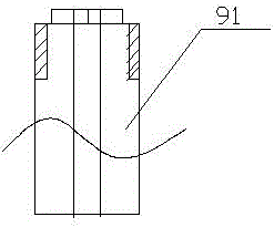
[0046] Such as Figure 5 Shown, another kind of support bolt construction method, comprises the following steps:

[0047] a. Tightly connect the inner threaded end of the anchor drill bit with the outer threaded end of the front end anchor rod, the anode end of the front end anchor rod body is connected to the cathode end of the injection-molded hybrid connector, start the anchor drill rig to connect the anchor drill bit and the front end anchor The rod body is slowly pushed into the anchor end face, and at the same time, water is injected into the through hole of the anchor rod from the water supply pipeline, part of the water is injected into the drill hole through the through hole, and part of the water flows out through the injection molding mixing connector through the drainage pipeline;

[0048] b. Reserve the anode end of the front-end bolt body, remove the injection-molded hybrid connector and the bolt rig, and close the external water injection;

[0049] c. Tightly c...


PUM


Abstract

The invention discloses an injection molding type anchor rod supporting device which comprises a supported anchor rod and an injection molding device. The supported anchor rod comprises a tail anchor rod body, a connecting sleeve, a front end anchor rod body, a conical rubber plug, a tray and a fastening nut. The injection molding device comprises an injection molding mixing connector, a two-position three-way reversing valve A, a two-position three-way reversing valve B, a pressure gage A, a pressure gage B, a hydraulic oil cylinder, a resin pulp barrel and a catalyst barrel. By means of the injection molding type supporting anchor rod device, a drill pipe is replaced with the anchor rod, supporting of the lengthened anchor rod is achieved, rod body full-length anchoring is achieved, the supporting procedure is simplified, it can be achieved that an anchoring agent is intelligently injected into multiple anchor rods at the same time, the supporting working efficiency and the supporting effect are greatly improved, operation is convenient and fast, universality and practicability are high, and epoch-marking significance is achieved on reformation of the supporting technology.

Description

technical field [0001] The invention relates to an injection-molded support bolt device and a construction method for mine roadway, tunnel or underground engineering. Background technique [0002] Bolt support is widely used in mine roadway, tunnel and underground engineering support. At present, the support bolts are all of a single structure, the bolt support process is cumbersome, the efficiency is low, and the full-length anchoring cannot be realized, and the support of the extended bolt cannot be realized due to space constraints, which restricts the realization of comprehensive mechanized rapid support. The reform of bolt support technology has been introduced. [0003] The injection-molded support bolt device changes the bolt from a single structure to a combined structure, which evolves from one original part to a plurality of main parts, which has all the characteristics of the bolt and drill, replacing the bolt and drill; the middle rod body The segments can be c...

Claims


Application Information

Patent Timeline
Patent Type & Authority Patents(China)
IPC IPC(8): E21D21/00E21D20/02E02D5/74
CPCE02D5/74E21D20/003E21D20/025E21D20/028E21D21/0046E21D21/0093
Inventor 李志黄胜周茂风
Owner 黄胜
Why Eureka
Try Eureka